What is injection molding?
What is injection molding and how does it work? In this comprehensive introduction, we cover the basic principles of this efficient and repeatable manufacturing technology. After reading this article you will understand the fundamental mechanics of the injection molding process and how these relate to its key benefits and limitations.
What is Injection Molding?
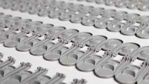
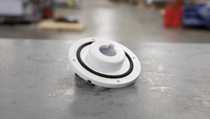
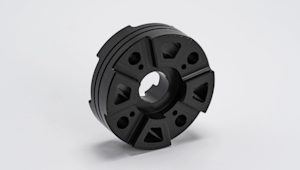
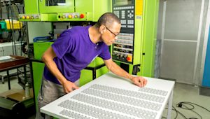
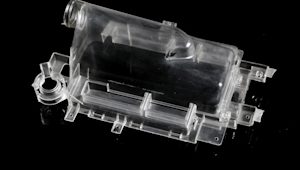
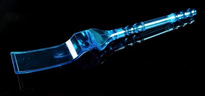
Injection Molding is a manufacturing technology for the mass-production of identical plastic parts with good tolerances. In Injection Molding, polymer granules are first melted and then injected under pressure into a mold, where the liquid plastic cools and solidifies. The materials used in Injection Molding are thermoplastic polymers that can be colored or filled with other additives.
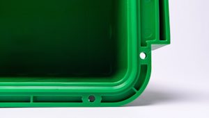
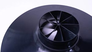
Almost every plastic part around you was manufactured using Injection Molding: from car parts, to electronic enclosures, and to kitchen appliances.
Injection Molding is so popular, because of the dramatically low cost per unit when manufacturing high volumes. Injection molding offers high repeatability and good design flexibility. The main restrictions on Injection Molding usually come down to economics, as high initial investment for the is required. Also, the turn-around time from design to production is slow (at least 4 weeks).
In this article, we will first see how injection molded parts are made and we will examine the basic characteristics of the process that are important to keep in mind when you design a part for Injection Molding. Next, we will delve deeper into the mechanics of the technology to understand how these are connected to its economics (through an example) and its key benefits and limitations.
Need advice on your Injection Molding project?
How does Injection Molding work?
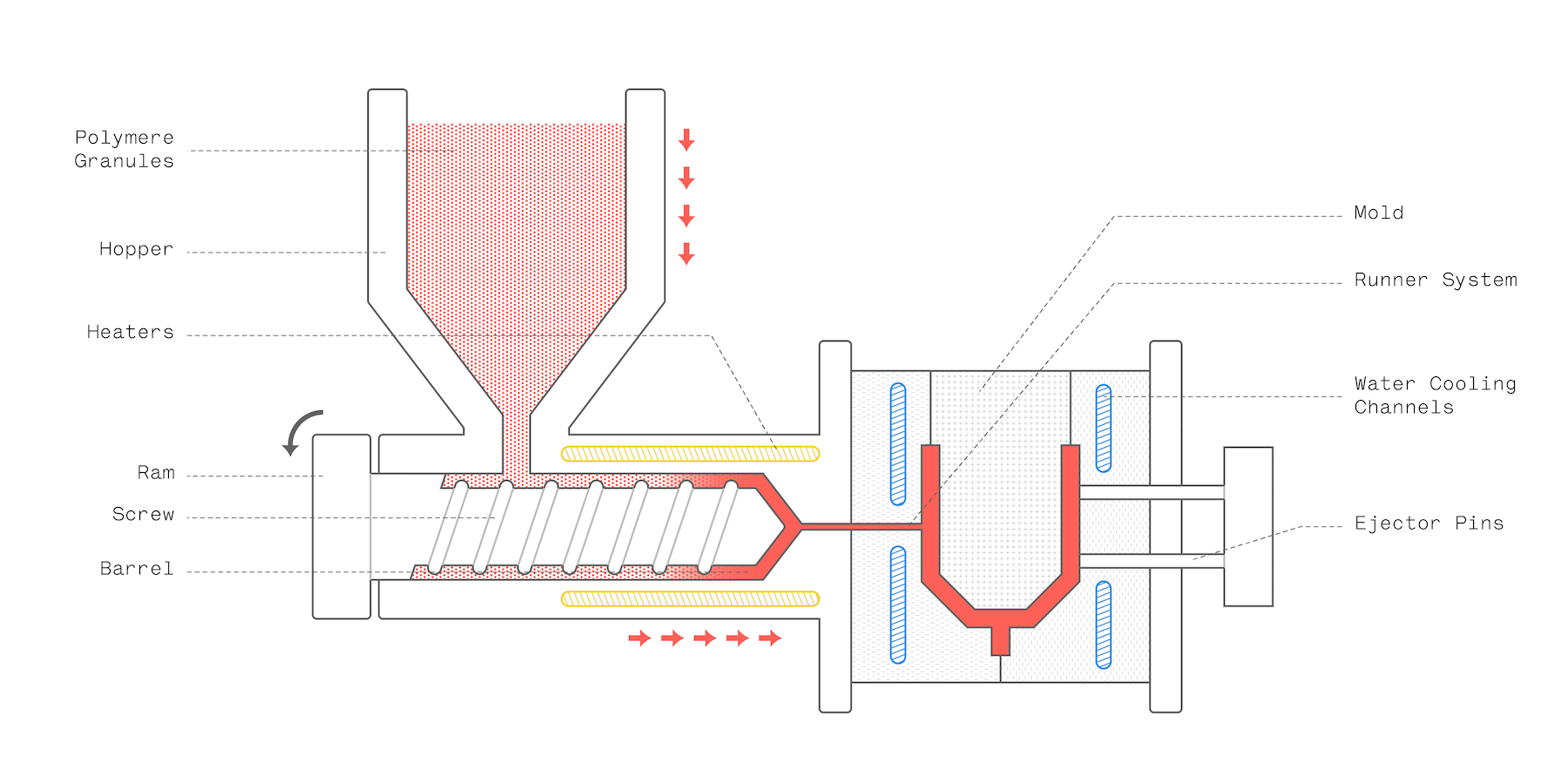
Here is how the Injection Molding fabrication process works:
- The polymer granules are first dried and placed in the hopper, where they are mixed with the coloring pigment or the other reinforcing additives.
- The granules are fed into the barrel, where they are simultaneously heated, mixed and moved towards the mold by a variable pitch screw. The geometry of the screw and the barrel are optimized to help build up the pressure to the correct levels and melt the material.
- The ram then moves forwards and the melted plastic is injected into the mold through the runner system, where it fills the whole cavity. As the material cools down, it re-solidifies and takes the shape of the mold.
- Finally, the mold opens and the now solid part is pushed out by the ejector pins. The mold then closes and the process repeats.
The whole can be repeated very fast: the cycle takes approximately 30 to 90 seconds depending on the size of the part.
After the part is ejected, it is dispensed on a conveyor belt or in a holding container. Usually, injection molded parts are ready to use right away and require little to no post-processing.
Characteristics of Injection Molding
Manufacturing the Mold
The mold is like the negative of a photograph: its geometry and surface texture is directly transferred onto the injection molded part.
It usually makes up the largest portion of the start-up costs in Injection Molding: the cost of a typical mold starts at approximately $2000-5000 for a simple geometry and relatively small production runs (1.000 to 10.000 units) and can go upwards to $100.000 for molds optimized for full-scale production (100.000 units or more).
This is due to the high level of expertise required to design and manufacture a high-quality mold that can produce accurately thousands (or hundreds of thousands ) of parts.
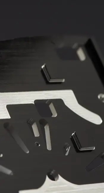
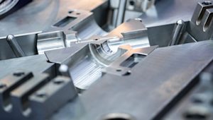
Molds are usually CNC machined out of Aluminum or Tool Steel and then finished to the required standard. Apart from the negative of the part, they also have other features, like the runner system that facilitates the flow of the material into the mold, and internal water cooling channels that aid and speed up the cooling of the part.
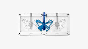
Recent advances in 3D printing materials have enabled the manufacturing of molds suitable for low-run injection molding (100 parts or less) at a fraction of the cost. Such small volumes were economically unviable in the past, due to the very high cost of traditional mold making.
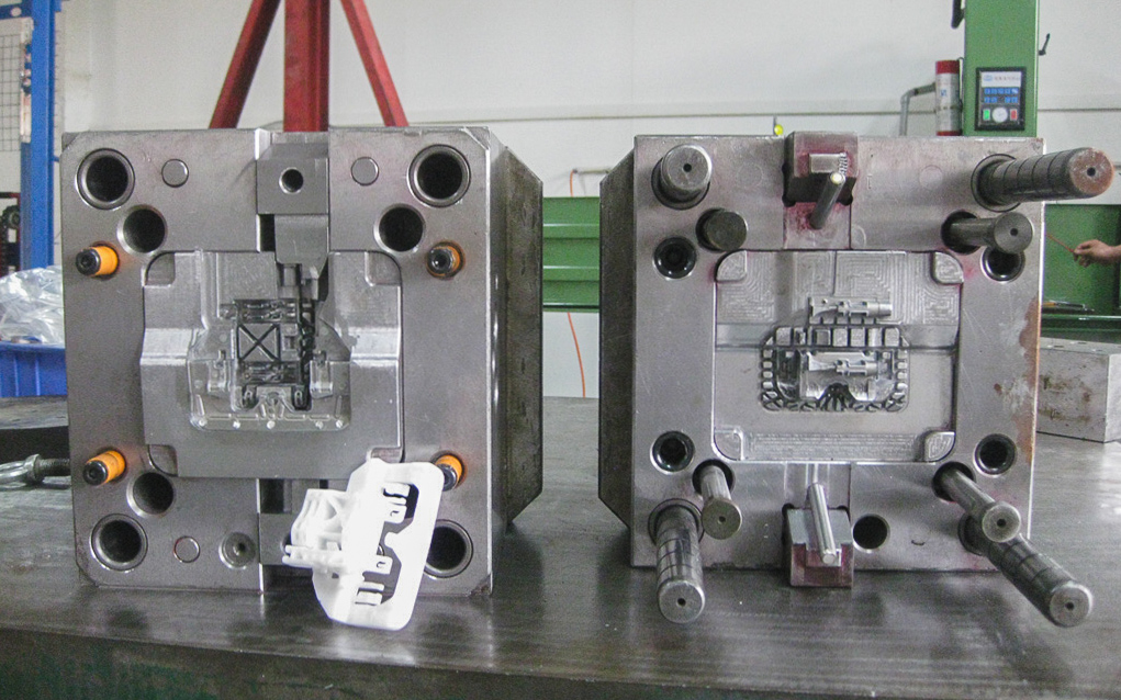
The Anatomy of a Mold
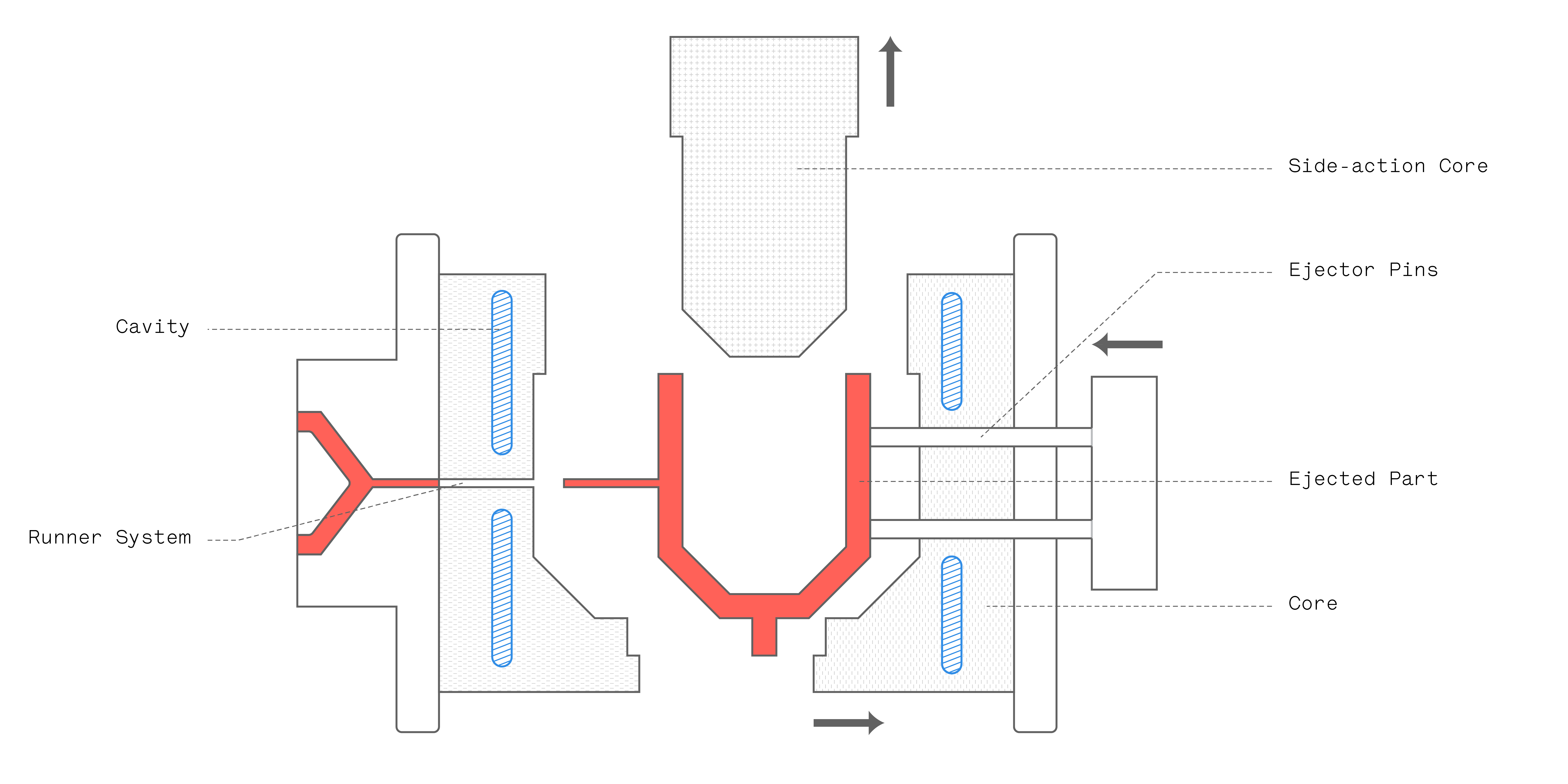
The simplest mold is the straight-pull mold. It consist of two halves: the cavity (the front side) and the core (the back side).
In most cases, straight-pull molds are preferred, as they are simple to design and manufacture, keeping the total cost relatively low. There are some design restrictions though: the part must have a 2.D geometry on each side and no overhangs (i.e. areas that are not supported from below).
If more complex geometries are required, then retractable side-action cores or other inserts are required.
Side-action cores are moving elements that enter the mold from the top or the bottom and are used to manufacture parts with overhangs (for example, a cavity or a hole). Side-actions should be used sparingly though, as the cost increases rapidly. More details on when to use them are given in a latter section.
The 2 Sides of the Mold: A side & B side
Injection molded parts have two sides: the A side, which faces the cavity (front half of the mold) and the B side, which faces the core (back half of the mold). These two sides usually serve different purposes:
- The A side usually has better visual appearance and is often called the cosmetic side. The faces on the A side will be smooth or will have a textured according to your design specifications.
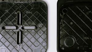
- The B side usually contains the hidden (but very important) structural elements of the part (the bosses, ribs, snap-fits and so on). For this reason it is called the functional side. The B side will often have a rougher finish and visible marks from the ejector pins.
Injecting Material into the Mold: the Runner System
The runner system is the channel that guides the melted plastic into the cavity of the mold. It controls the flow and pressure with which the liquid plastic is injected into the cavity and it is removed after ejection (it snaps off).
The runner system consists of three sections: the sprue, the runner and the gate.
- The sprue is the main channel in which all the melted plastic initially flows through as it enters the mold.
- The runner spreads the melted plastic along the face where the two halves of the mold meet and connects the spur to the gates. There may be one or more runners, guiding the material towards one or multiple parts.
- The gate is the entry point of the material into the cavity of the mold. Its geometry and location is important, as it determines the flow of the plastic.

There are four types of gates used in Injection Molding:
- Edge gates inject material at the parting line of the two halves of the mold and are the most common gate type. The runner system has to be removed manually later, leaving a small imperfection at the injection point.
- Tunnel gates inject material below the parting line. The runner system snaps off as the part is ejected from the mold, eliminating the need for manual removal. This makes this type of gate ideal for very large volumes.
- Post gates inject the material from the backside of the cavity, hiding the small imperfection left from breaking the other gate types. These gates are used for parts that require excellent visual appearance.
- Hot tips are directly connected to the spur and inject plastic from the top side of the part. No material is wasted this way on the runner system making them ideal for large scale production, but a dimple will be visible at the injection point.

Designing a part for Injection Molding
The Injection Molding process offers great design flexibility, but the characteristics of the flow lead to some restrictions that may not be so intuitive.
Here is a list of the most important design guidelines you should have in mind when you start designing an Injection Molding part:
- Use uniform wall thickness throughout the part. A wall thickness between 1.2 mm and 3 mm is a safe value (for any material you might use). If sections of different thickness are needed make the transition as smooth as possible, using a chamfer or fillet. This way, the material flow will even everywhere inside the cavity, ensuring that the whole mold will be fully filled.
- Hollow out thick sections (and use thin ribs). Thick sections can lead to various defects (as we will see in a bit). To improve strength, add ribs instead of increasing the thickness of the part. This way you will limit the deformation as the part cools down and contracts.
- Add a draft angle of at least 2o to all vertical walls of your part. This will make ejection easier. Vertical walls without draft angles will have drag marks on their surface, due to the high friction with the mold during ejection. Larger draft angles (up to 5o) are required for features taller than 50 mm or for walls with textured surfaces.
- Round all the edges of your part. For interior edges, use a radius of at least 0.5x the wall thickness. For exterior edges, add a radius equal to the interior radius plus the wall thickness. This way you ensure that the thickness of the walls is constant everywhere (even at the corners).
An article dedicated to designing guidelines for Injection Molding can be found here.

When to use Side-actions Cores
We saw previously that the basic straight-pull mold is capable of producing most injection molding geometries, but sometimes side-action cores are required.
Side-action cores are inserts that slide in as the mold closes and slide out before it opens. As the name implies, they are moved into position by a mechanism from one of the sides of the mold (usually from above or from below). This way parts can be created that have features with overhangs (for example side holes or snap fit joints).
Here are some requirements that features designed for side actions must meet:
- There needs to be space for the core to move in and out. This means that the feature must be on the outside of the part
- The side-actions must move perpendicularly. Moving at an angle other than 90o is more complicated, increasing cost and lead times.
- Don’t forget to add draft angles to the side action core as usual.
How to avoid Common Defects in Injection Molding
It is common for injection molded parts to have some small imperfections after they come out of the machine.
For example, injection molded household products sometimes have a visible parting line, ejector marks (on their B side) or blemishes from trimming the gate. If high visual appearance is required, then these imperfections can be sanded off or hidden away during mold design.

More serious defects in injection molding are connected to the design of the mold and the properties of the material. Since the cost of the mold is high, getting it right from the first time is very important. Below is a list of the most common defects and some recommendations on how to avoid them. Keep in mind that all these defects can be avoided by following good design practices for injection molding.
Warping:
Warping occurs when the part deforms unevenly as the material cools down and shrinks. This results in the bending of some features (or the whole part). To prevent warping:
Sinking:
Sinking occurs when the middle of the face contracts (sinks) towards the center as it cools down. This again occurs due to the uneven cooling of the part. To prevent sinking:
Weld lines:
When two or more separate flows meet, they may not fully blend together, resulting in local deformation or discoloration of the part, known as weld lines. This defect occurs when the part has many holes or other features that split the flow or when the plastic is injected through multiple gates. To prevent weld lines:
Underfills & burn marks:
At dead-end areas (for example at the far end of deep ribs or bosses), air might get trapped during injection, stopping the mold from filling completely, resulting in an underfilled part. Alternatively, the temperature of the trapped air might rise and cause a burn mark on the surface of the part. To avoid underfills and burn marks:
Injection Molding Materials
One advantage of Injection Molding is the huge range of compatible plastic materials. Most thermoplastics can be injection molded. Moreover, the standard thermoplastics can be reinforced with fibers, rubber particles, minerals, flame retardants or blended with other thermoplastic.
A list of the most commonly used injection molding materials is given in the table below. Keep in mind that the cost of bulk thermoplastic pellets varies greatly from about $7-10 per kilo for ABS and HDPE, up to $140 per kilo for PEEK and PEI.
| Material | Characteristics |
|---|---|
| ABS |
High impact resistance
Low cost
Vulnerable to solvents
Common applications: consumer products, enclosures
|
| Nylon (PA 6, 66 & 11) |
High strength
High chemical resistance
Absorbs moisture
Common applications: automotive components, gears
|
| HDPE |
Can produce very fine details
High impact resistance
Low strength
Common applications: consumer products, medical products
|
| Delrin (POM) |
High strength & stiffness
Self lubricating
Prone to warping during injection
Common applications: mechanical components, household appliance
|
| Polycarbonate (PC) |
Excellent impact resistance
High heat resistance
Subject to stress cracking
Common applications: automotive headlights, consumer products
|
| ABS/PC |
Excellent impact resistance & thermal stability
High toughness
Vulnerable to solvents
Common applications: automotive components, electronic housings and enclosures
|
| PEI (Ultem) |
High-performance thermoplastic
Excellent heat & flame resistance
High cost
Common applications: aerospace components, medical products
|
| PEEK |
High-performance thermoplastic
Excellent mechanical properties & chemical resistance
High cost
Common applications: aerospace components, oil & gas
|
| Polystyrene (PS) |
Lowest cost thermoplastic
Food-safe grades available
Poor mechenical properties
Common applications: household appliance, packaging
|
| Polypropylene (PP) |
Excellent chemical & moisture resistance
Food-safe grades available
Loose tolerances
Common applications: fluidics, packaging
|
An additive that is commonly used to improve the stiffness of the injection molded parts is fiberglass. The glass fibers can be mixed with the pellets at ratios of 10%, 15% or 30%, resulting in different mechanical properties.
Colorant can be added to the mixture (at a ratio of about 3%) to create a great variety of colored parts. Standard colors include red, green, yellow, blue, black and white and they can be mixed to create different shades.
Post processing & finishes
Usually, injection molded parts are ready to use and post-processing is limited to trimming away the runner system. Critical features of injection molded parts can also be machined to achieve tighter tolerances.
The mold itself can be finished to different standards. The table below lists the most common finishes used in mold manufacturing. For more details and recommendations, you can refer to the SPI surface finishes guide in the appendix.
| Finish | Characteristics |
|---|---|
| As-machined finish |
Tool marks will be visible on the surface of the injection molded part. Suitable for non-cosmetic parts. |
| Matte finish |
The mold is sanded with gritstone and the tool marks are removed. Some sanding lines might be visible. |
| Semi-glossy finish |
The mold is first sanded with gridstone and then hand polished with a grit paper. Good visual appearance, but not a high glossy look. |
| Glossy finish |
The mold is first sanded then polished with a diamond buff (supension). Smooth mirror-like finish |
| Textured |
The mold is sand blasted removing all tool marks and adding a light texture. Cosmetic matte finish |

Estimating the Cost of Injection Molding (with an example)
The cost per part in Injection Molding can be estimated using the following formula:
Cost per Part = Cost of Material + Cost of Tooling / Number of parts + Hourly Costs / Production Time
The main cost driver in Injection Molding is the cost of tooling. Of course, the more parts you make, the more this cost spreads and the lower the cost per part will be.
The cost of material is constant per part and it is relatively low, as the bulk cost of most injection molding pellets is actually very small. When you estimate the weight of your part, don’t forget to take also into account the runner system.
The hourly costs include machine and labor costs. These are dependant on the geographic location that the production takes place and the size of the manufactured part (larger parts require higher pressures and thus a more expensive machine)
Let’s put this knowledge into practice a small example:
Let’s assume that you are designing a part optimized for injection molding with dimensions of 200 mm x 200 mm x 4 mm and weight of approximately 50 grams.
For a part this large, it is assumed that the cost of the mold will be approximately $30.000. It is a household device and we would not require a very expensive material, so we estimate a cost of $10 per kg as a reasonable assumption (typical for higher grade ABS or HDPE pellets).
For the hourly costs, we can assume a cycle time of 80 seconds, which means that 45 parts per hour will be produced and that a combined hourly machine and labor cost of approximately $30.
With these assumptions we can plot the following graph:

The cost per part drops fast for volumes below 5.000 parts and reaches a plateau of approximately $2 per part for volumes above 20.000 units. For lower volumes, the cost is mainly dictated by the cost of the mold. For example, if only 1000 parts were manufactured, their unit cost would be $30. The cost of the mold can be reduced, by reducing the complexity of the part. This makes injection molding of lower volumes (down to 1000 parts) economically viable.
3D printing can be used to manufacture low-run injection molds and reduce the cost. The drawback of these molds is that they fail after a few hundred runs, so they are most suitable for prototyping purposes or small-scale production.
Curious about the costs of Injection Molding?
Benefits & Limitations of Injection Molding
The key advantages and disadvantages of the technology are summarised below:
Rules of Thumb
- Use 3D printing or CNC machining to prototype and finalize your designs before you go to production with Injection Molding.
- The main cost driver in Injection Molding is the mold, which is a result of the part geometry. The simpler the part, the cheaper the mold.
- To avoid defects, keep wall thickness constant, add draft angles to vertical walls and round all corners.
- Injection molding is economically viable for volumes larger than 1000 parts, but other solutions also exist that can reduce the cost per unit for smaller volumes.
