Simulations in 3D printing
Learn about the benefits and current state-of-the-art of 3D printing simulations. This article describes why, what and how to use simulations in 3D printing and gives tips to help you get started.
Introduction
Simulating the fabrication process is slowly becoming part of the 3D printing workflow. 3D printing simulations help to understand and visualize the complex thermo-mechanical phenomena taking place during manufacturing, resulting in the production of high-quality, high-accuracy parts.
This is especially important for high-value components fabricated using state-of-the-art 3D printing process, where design iterations (discarding a defective print) are very expensive in terms of both material cost and manufacturing time.
Simulations of the 3D printing process should not to be confused with the more common mechanical FEA simulations: The latter helps evaluate the mechanical performance of a part under certain conditions related to its function (load, deformation, temperature etc), while the former helps predict the result of the 3D printing manufacturing process, layer-by-layer and under certain process parameters.
In this article we first present the main benefits of simulating each of the 3D printing processes and then we take a closer look at the details of running a successful simulation, giving some handy tips to get you started.
Why use simulations in 3D printing?
Simulating the 3D printing process is very valuable, because it helps to:
You can perform the simulation before or after generating the support structures:
Before support generation, simulation results help identify critical areas of significant deformation or internal stress during manufacturing. The designer can then add adapted support structures to minimize the deformation, change the print orientation to change the areas of heat accumulation or modify the geometry of the 3D model to improve the quality of the end result.
After support generation, simulations help minimize the risk of production failure (for example due to recoater interference), ensure that the dimensions of the final part lie within a specified tolerance range and evaluate the impact of different print parameters (for example, by comparing parameters optimised for production versus parameters optimised for accuracy).
In both cases, simulations aid in reducing the risk associated with high-value manufacturing and to improve the productivity of high-volume 3D printing, saving weeks of production time and thousands of dollars in development and production costs.
Which 3D printing processes to simulate?
Simulations are most relevant for high-value and high-precision 3D printing. Moreover, the most popular contemporary 3D printing simulation packages are based on metal welding simulation solvers. Thus simulations are more commonly used with metal 3D printing.
However, all main 3D printing processes can be simulated and here is why:
SLM/DMLS: SLM and DMLS are the oldest and most mature technologies among metal 3D printing processes and, therefore, many software packages focus primarily on them. Because the fusion temperatures of metals are higher than the polymer sintering temperatures, the thermo-mechanical constraints in SLM/DMLS parts are most important.
EBM: EBM is a more recent metal 3D printing technology compared to SLM/DMLS and only a few software packages provide solutions for it. Simulations in EBM can help identify the heat accumulation regions generated from the electron beam.
FDM: The main issue with FDM is warping, which occurs due to differential cooling of the extruded thermoplastic material. Simulation can help check whether the part needs to be redesigned or whether a brim should be added to increase the adhesion to the platform.
SLA/DLP: In SLA and DLP the main issue is curling, which is similar to warping. Not many software solution exist to simulate the SLA printing process at the moment.
SLS: In SLS, support structures are not required, but zones of thermal accumulation can appear in the build, resulting in poor surface smoothness or warping. Simulation can help identify these areas.
Simulation outputs & results
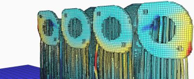
Temperature distribution
The gradient of temperature is the root cause of all the mechanical phenomena occurring during a build.
The temperature gradient can sometimes be computed alone, without any mechanical deformation. It is usually quicker than a full simulation and solving the heat accumulation issues might at the same time solve the mechanical deformation problems.

Temperature gradient distribution of a descretized model (SLM/DMLS) in Netfabb. Courtesy Poly-Shape
Deformation
Assuming that the true mechanical properties of the material are known, the deformation of the part during manufacture can be calculated.
The direction of the deformation are usually correct no matter what simulation parameters are used, but the amplitude of the deformation is closely dependent on the size of the simulation mesh: using a finer mesh will yield more precise results, but requires more time to run.

Deformation vectors of a model (SLM/DMLS) in Netfabb. Courtesy Poly-Shape
Recoater interference
In powder bed technologies (such as SLS and SLM/DMLS), if the deformation along the z-axis is larger than the layer thickness, the recoater can come in contact with the part, sweeping it away and causing a failure. In some simulation packages, you can define the height of the recoater tolerance and the software will warn you in case a deformation along the z-axis exceeds that threshold.
Post processing steps
The primary focus of the 3D printing simulation packages is the computation of thermo-mechanical phenomena occurring during the fabrication of a part. However, other problems can also appear in later steps of the manufacturing process.
During the detachment of the part from the build platform or the removal of the support structures, the residual stress from the manufacturing process can cause the part to deform. Heat treatments can help relieve the internal stress. Some simulation packages allow you to simulate these post-processing steps and help evaluate whether a heat treatment is necessary (or even effective).
List of simulation software
Discretization
The first step of a good simulation is the correct discretization of the part volume.
Unlike regular mechanical simulation, which uses conformal meshing with tetrahedrons, most 3D printing simulation software use voxelization. the 3D volume of the part is represented by small cubes (or voxels), in a similar way that a 2D image in a PC monitor is represented by square pixels. Using more meshing elements produce more precise results, but also increases significantly the simulation time. Finding the right balance is key.
For an initial simulation, it can be interesting to launch a first coarse simulation, with large voxels, in order to obtain “quick and dirty” results. Such a simulation should enable you to obtain in a matter of seconds or minutes the main deformation areas of your print. It will not cost you much and can help you decide if a more precise simulation (with smaller voxels) is necessary.
Material & print parameters
Once the part is discretized, you need to select the material properties. Defining the material properties is probably the most crucial step in the simulation process, as inaccurate data will produce wrong simulations results.
Most editors provide their own material library, which can be really helpful to get you started.
In both cases, they are probably not perfectly adapted for simulations. Every simulation software allows you to modify or create your own materials to generate the most accurate simulations. This requires expert material science knowledge to be done correctly and it is not recommended for inexperienced users.
Calibration
Some simulation software allows you to calibrate the material properties based on test specimens printed in a specific material and on a specific machine. This way, more precise material properties are identified, resulting in more accurate simulation results.
Key steps for a successful simulation
There are two types of simulation software: cloud based solvers and local solvers.
Cloud based solvers are usually faster than local solvers, as they are not restricted by the computational capabilities of your computer. However, some companies are reluctant to use cloud based solvers due to confidentiality issues, as data sent through the Internet could be more easily compromised. For most application this would not be an issue.
Here is a list of some of the most popular 3D printing simulation software:
| Software | Type | Supported Processes |
|---|---|---|
Amphyon
 |
Local | SLM/DMLS |
Comsol
 |
Local | SLM/DMLS, SLS, FDM |
ESI
 |
Local | SLM/DMLS |
exaSIM
 |
Cloud-based | SLM/DMLS |
Netfabb
 |
Local & Cloud-based | SLM/DMLS |
Simufact
 |
Local | SLM/DMLS, EBM |
GeonX
 |
Local | SLM/DMLS |
EX Digimat-AM
 |
Local | SLS, FDM |
Rules of Thumb
- Simulate before support generation to improve part geometry and to aid with the design of supports.
- Simulate after support generation to validate accuracy and to check for recoater interference.
- First run a quick simulation with large voxels to identify areas of larger deformation. Then refine the mesh to improve accuracy of the results.
- Simulate temperature without mechanical resolution to save time, as solving the heat accumulation issues might also solve mechanical deformation problems.
- Prefer cloud based simulation software for faster performance, but use local solvers if needed to comply with confidentiality policies.
