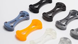
Fused deposition modeling, also known as fused filament fabrication, is an additive manufacturing process in the material extrusion family. The printer heats a thermoplastic filament and deposits it in a programmed path to build parts layer by layer. Each layer fuses to the previous one as the material cools, producing a solid geometry from a digital CAD model.
FDM accounts for the largest installed base of 3D printers worldwide. It is the most widely used additive technology across industries and is often the first process engineers consider for 3D printing.
Curious about the price of FDM 3D printing?
Our FDM 3D printing services Upload a CAD for a free, instant FDM quote
This article explains the basic principles and key characteristics of FDM, compares desktop and industrial systems, and provides practical guidance for engineers to optimize parts for outsourced FDM production.
Watch before you read: how to prototype like a pro with FDM 3D printing
This video explains how to use FDM 3D printing for rapid prototyping and offers practical tips for engineers outsourcing parts.
How does FDM 3D printing work?
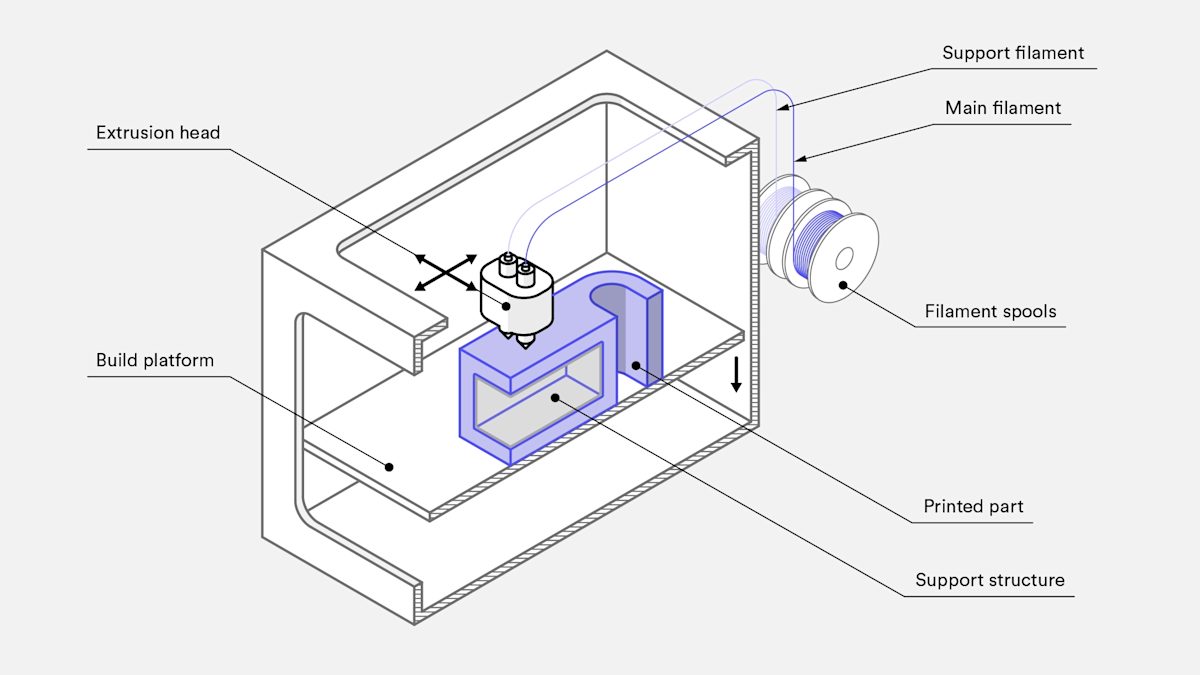
FDM 3D printing builds parts by depositing melted filament onto a build platform, layer by layer, until the part is complete. The process starts with a digital design file that is translated into machine instructions. Common FDM materials include ABS, PLA, PETG, and PEI, supplied as filament on spools and fed into a heated nozzle.
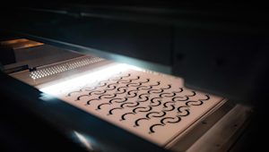
When the nozzle reaches the target temperature, the filament is pushed through the extrusion head and melted. The extrusion head is mounted on a three-axis system that moves the nozzle across the X, Y, and Z axes. Melted material is extruded in thin strands and deposited along the programmed toolpath. Each strand cools and fuses to the previous layer to form a solid geometry.
Filling an area requires multiple passes, similar to shading a shape with a marker. After one layer is finished, the build platform lowers or the extrusion head moves, and the next layer is printed. Fans are sometimes used at the extrusion head to speed cooling and improve layer adhesion. The cycle repeats until the full part is produced.
What are the print parameters for FDM 3D printers?
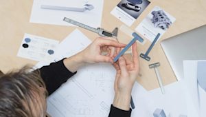
Most FDM systems allow control of several process parameters, including nozzle temperature, build platform temperature, print speed, layer height, and cooling fan speed. In outsourced production, these settings are typically managed by the additive manufacturing operator, but designers should understand how they affect parts.
Build size and layer height are key considerations. Typical desktop build volumes are around 200 x 200 x 200 mm, while industrial machines can reach about 1,000 x 1,000 x 1,000 mm. Large models intended for desktop printers can be split into smaller sections and reassembled after printing.
Layer height commonly ranges from 50 to 400 microns. Shorter layers give smoother surfaces and better fidelity on curved features, while taller layers reduce print time and cost.
Design tip: A practical compromise is a 200 micron layer height. For more detail, see our article on the impact of layer height on 3D printed parts.

Is there a difference between desktop and industrial FDM printers?
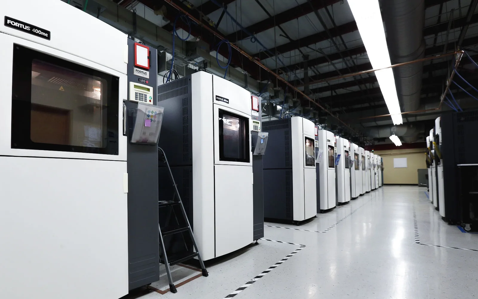
FDM printers fall into two main categories: industrial (professional) and desktop (prototyping). The primary difference is scale and repeatability. Industrial machines cost more than desktop systems but offer larger build volumes, higher reliability, and consistency suited to tooling, functional prototypes, and low-volume production runs. They run with minimal operator intervention and deliver faster throughput for larger orders.
Industrial FDM systems, such as Stratasys machines, cost significantly more than desktop units, which are generally used for bench‑top prototyping. Industrial printers offer larger build volumes, tighter process control, and greater repeatability, and they support engineering‑grade thermoplastics. For these reasons they are commonly used for tooling, functional prototypes, and end‑use parts. Desktop FDM remains useful for quick concept models and early design iterations, but industrial FDM is the preferred choice when engineers need consistent quality and higher throughput for outsourced production.
Industrial FDM printers handle larger orders faster than desktop machines. They are built for repeatability and reliability and can produce the same part repeatedly with minimal operator intervention. Desktop FDM systems are better suited to quick concept models and early iterations but require more frequent maintenance and calibration.
In the table below, we compare the main differences between a typical desktop FDM machine and an industrial system.
| Property | Industrial FDM | Desktop FDM |
|---|---|---|
| Standard accuracy | ± 0.3% (lower limit: ± 0.2 mm) | ± 0.5% (lower limit: ± 1.0 mm) |
| Typical layer thickness | 0.18 - 0.5 mm | 0.10 - 0.25 mm |
| Minimum wall thickness | 1 mm | 0.8 - 1 mm |
| Maximum build envelope | Large (e.g. 900 x 600 x 900 mm) | Medium (e.g. 200 x 200 x 200 mm) |
| Common materials | ABS, PC, ULTEM | PLA, ABS, PETG |
| Support material | Water-soluble/Break-away | Same as part (typically) |
| Production capabilities (per machine) | Low/Medium | Low |
| Machine cost | $50000+ | $500 - $5000 |
What are the characteristics of FDM 3D printing?
FDM 3D printers vary in extrusion systems and the part quality they produce, but they share common characteristics across processes. These include layer-by-layer deposition, visible tool paths, and consistent material behaviour that engineers can account for when outsourcing parts.
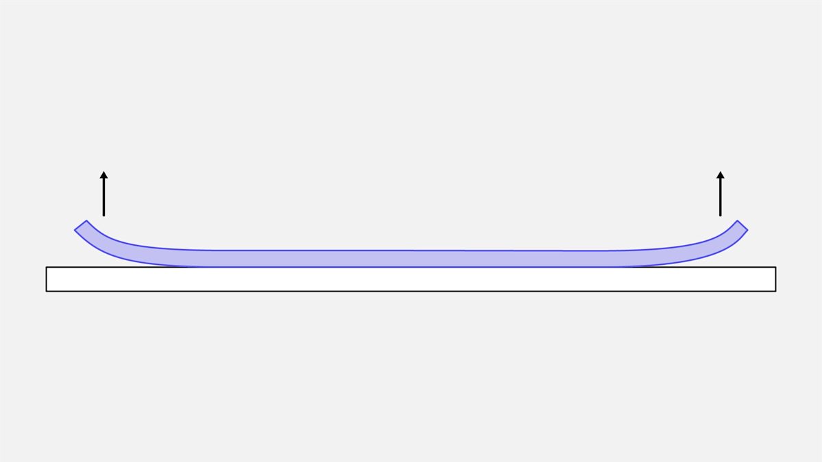
Warping
Warping is a common defect in FDM. As extruded material cools it shrinks, and different sections cool at different rates. This differential cooling generates internal stresses that lift underlying layers and cause the part to warp.
To reduce warping, control system temperatures—particularly the build platform and chamber—and increase adhesion between the part and the build platform.
Making certain design choices can lower the risk of warping during FDM printing:
-
Avoid large flat areas where possible. Broad, planar surfaces such as box faces are more likely to lift or deform.
-
Reduce thin protruding features. Narrow prongs and fins are prone to warping. Increasing the contact area at the base or adding support material helps stability.
-
Add fillets to sharp corners. Rounded transitions reduce stress concentration and are less likely to warp than sharp edges.
-
Match material to geometry. Different polymers have different sensitivities to warping. For example, ABS is generally more prone to warping than PLA or PETG.
Layer adhesion
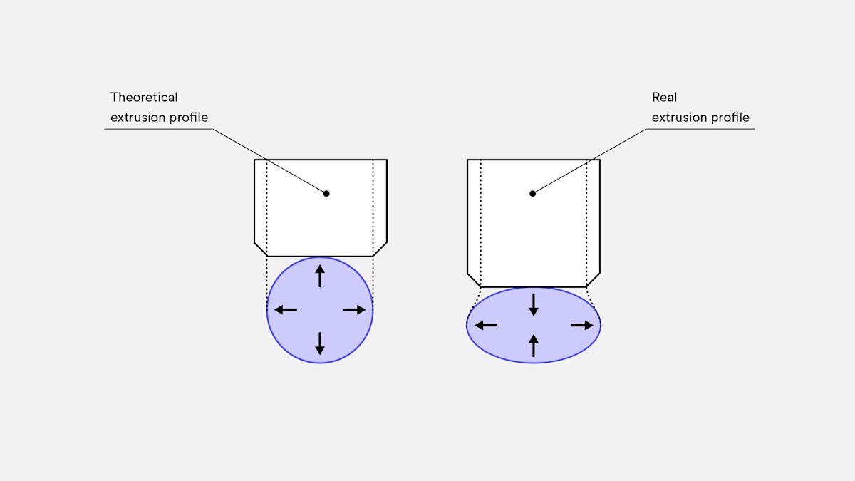
Strong bonding between successive layers is critical in FDM. As molten thermoplastic is extruded, the new material presses against the previous layer. Heat and pressure cause slight remelting, which fuses the layers together.
Because the deposited strand is deformed by contact with the layer beneath, its cross section becomes slightly oval. This produces a characteristic wavy surface texture regardless of layer height. Small features such as fine holes or threads may therefore require post-processing to meet tight dimensional or surface finish requirements.
Support structure
FDM printers cannot deposit molten thermoplastic across unsupported gaps. Certain geometries require support structures, which are usually printed in the same material as the part.
Removing supports can be difficult, so designs that minimise the need for supports are preferable. Dissolvable support materials are available for higher‑end FDM systems, but they increase overall print cost.
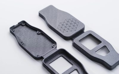
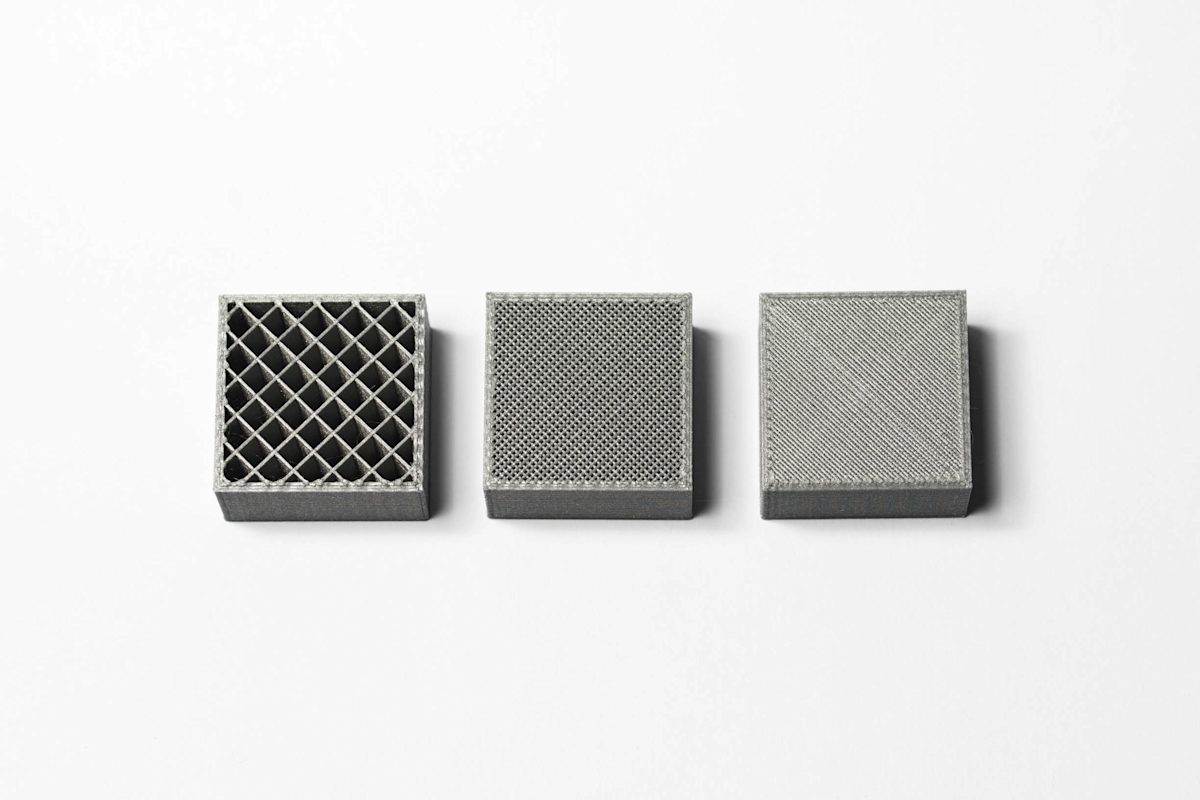
Infill and shell thickness
FDM printers normally do not produce fully solid parts to save time and material. The machine traces the outer perimeter, called the shell, over multiple passes and fills the interior, called the infill, with a low density structure.
Infill and shell thickness directly affect part strength, weight, and build time. A common desktop default is 20 percent infill with a 1 mm shell, which balances strength and speed for rapid prototypes.
The table below summarizes the main characteristics of FDM 3D printing.
| FDM | |
|---|---|
| Materials | Thermoplastics (PLA, ABS, PETG, PC, PEI etc) |
| Dimensional Accuracy | ± 0.5% (lower limit ± 0.5 mm) - desktop ± 0.15% (lower limit ± 0.2 mm) - industrial |
| Typical Build Size | 200 x 200 x 200 mm - desktop 900 x 600 x 900 mm - industrial |
| Common layer thickness | 50 to 400 microns |
| Support | Not always required (dissolvable available) |
What are common materials for FDM 3D printing?
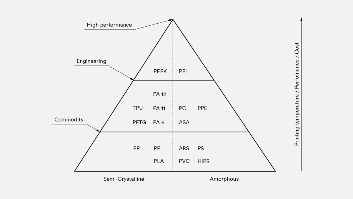
FDM supports a wide range of thermoplastics used for prototyping and production. Common categories include commodity polymers such as PLA and ABS, engineering materials like PA (nylon), TPU, and PETG, and high performance thermoplastics such as PEEK and PEI.
PLA is the most common filament for desktop FDM. It prints easily and captures fine detail, making it suitable for visual prototypes and concept models. ABS offers higher strength, ductility, and thermal stability for functional prototypes and end use parts, but it is more prone to warping on machines without a heated chamber. PETG combines ease of printing with mechanical properties similar to ABS, so it is a good middle ground for many applications.
PETG is a common desktop FDM alternative to ABS, offering similar composition and printability. PLA, ABS, and PETG suit most 3D printing service applications, from rapid prototyping and form, fit, and function testing to low volume production of models and functional parts.
Industrial FDM machines typically use engineering thermoplastics such as ABS, polycarbonate (PC), and Ultem. These materials often include additives that improve impact strength, thermal stability, chemical resistance, and biocompatibility.
Material choice affects part mechanical properties, dimensional accuracy, and cost. A comparison of common FDM materials appears in the table below.
| Material | Characteristics |
|---|---|
| ABS | + Good strength + Good temperature resistance - More susceptible to warping |
| PLA | + Excellent visual quality + Easy to print with - Low impact strength |
| Nylon (PA) | + High strength + Excellent wear and chemical resistance - Low humidity resistance |
| PETG | + Food Safe* + Good strength + Easy to print with |
| TPU | + Very flexible - Difficult to print accurately |
| PEI | + Excellent strength to weight + Excellent fire and chemical resistance - High cost |
For more details, see our review of the main differences between PLA and ABS and a full comparison of common FDM materials.
Post-processing for FDM 3D printing
FDM parts can be finished to a high standard using methods such as sanding and polishing, priming and painting, cold welding, vapor smoothing, epoxy coating, and metal plating. These processes improve surface appearance and functional performance for prototypes and low-volume production.
Interested in exploring all post-processing options for your next production run? Read our extensive guide to what’s available.
What are the best practices for printing with FDM?
-
Use FDM for rapid prototypes and low-volume functional parts when cost and speed are priorities.
-
Select materials based on mechanical, thermal, and chemical requirements; FDM supports commodity, engineering, and high-performance thermoplastics.
-
Note typical desktop build volume of 200 x 200 x 200 mm; industrial machines offer substantially larger build areas.
-
Design to reduce warping: avoid large flat faces and add fillets to sharp corners.
-
Account for anisotropy: FDM parts are weaker across layer lines, so avoid using FDM for mechanically critical components without validation.
-
Respect minimum feature limits set by nozzle diameter and layer height.
-
Vertical features in Z cannot be smaller than the chosen layer height, typically 0.1 to 0.2 mm.
-
Planar features in the XY plane are limited by nozzle diameter, commonly 0.4 to 0.5 mm.
-
Minimum wall thickness should be about two to three times the nozzle diameter, typically 0.8 to 1.2 mm.
-
Increase wall thickness or infill for load-bearing sections rather than relying on thin walls.
-
For very smooth surfaces or fine detail, expect additional post-processing such as sanding, vapor smoothing, or machining.
-
For high-detail cosmetic parts, consider SLA or other additive technologies instead of FDM.
If you are ready to get parts into production, visit Protolabs Network for an instant quote and onboard DFM analysis. For more information or to be matched with a specialized account manager, email networksales@protolabs.com .
Frequently asked questions
What are the advantages of FDM 3D printing?
FDM is a cost effective additive process that supports a wide range of thermoplastic materials. It offers fast turnaround for prototypes and low volume production, straightforward material tradeoffs for strength and flexibility, and predictable scaling from desktop to industrial systems.
What are the disadvantages of FDM 3D printing?
FDM is cost effective but delivers lower resolution and visible layer lines compared with other 3D printing technologies. That makes it less suitable for parts that require fine detail or a smooth, high‑quality surface finish.
Does FDM require post-processing?
FDM-printed parts typically show visible layer lines, so post-processing is usually required to achieve a smooth finish.
How accurate is FDM?
Part accuracy depends on printer calibration and the complexity of the model. Industrial FDM systems produce more accurate parts than desktop machines, though consumer printers are improving.
How expensive is FDM?
FDM is the most cost effective method for producing custom thermoplastic parts and prototypes. Desktop FDM is the cheapest option but yields lower quality parts than industrial FDM machines, which cost more but deliver better accuracy, repeatability, and material performance.
What materials are available for FDM?
FDM supports a wide range of thermoplastics for prototyping and production, including PLA, ABS, TPU, PETG, and PEI.
How fast is FDM?
FDM offers fast turnaround for custom thermoplastic parts. Typical lead times are a few days, depending on part size, quantity, and any required post-processing.
What is FDM mainly used for?
FDM is well suited to prototyping, modeling, and low-volume production. Desktop systems support rapid concept models and design iteration. Industrial FDM machines are used for functional prototypes, tooling, and low-volume end-use parts when engineering materials and repeatability are required.
Why is FDM currently the most popular 3D printing technology?
FDM is popular because it produces durable parts from engineering thermoplastics while retaining useful mechanical properties. Both desktop and industrial systems deliver good dimensional accuracy, and FDM remains more cost effective than many other additive processes for prototyping and low volume production.