3D printers are enormously flexible in the kinds of parts they can produce. Depending on the type of printing technology, you can manufacture parts of many different sizes and geometries. However, even the most advanced 3D printing methods have their limitations.
This article explores geometric and size limitations you should understand when designing 3D models in CAD to be manufactured with additive technologies. These limitations are important to consider whether you’re producing basic mechanical components or super complex parts (and anything in between).
We also have a comprehensive step-by-step guide on exporting your 3D models into the STL file format.
What’s the typical build size of 3D printers?
One of the major limitations that every 3D printing technology faces is the size of the part it can create.
Of course, this will differ depending on the kind of printer you’re using to manufacture parts, though a good rule of thumb is to use an industrial printer for more sizable parts. We also recommend splitting parts into two or more components to be printed separately and assembled after. Both of these options will affect the final cost.
The table below showcases the typical build size of the 3D printing processes we offer at Protolabs Network (and through Protolabs in the case of metal 3D printing).
| Typical build size | |
|---|---|
| FDM | 200 x 200 x 200 mm for desktop printers; Up to 900 x 600 x 900 mm for industrial printers |
| SLA | 145 x 145 x 175 mm for desktop printers; Up to 1500 x 750 x 500 mm for industrial printers |
| SLS | 300 x 300 x 300 mm (up to 750 x 550 x 550 mm) |
| DMLS/SLM | 250 x 150 x 150 mm (up to up to 500 x 280 x 360 mm) |
| MJF | 380 x 285 x 380 mm (14.9’’ x 11.2’’ x 14.9’') |
Minimum wall thickness for optimal printability
Another major factor to keep in mind when designing a part for 3D printing is the thickness of all the walls. Every 3D printing process has a standard minimum wall thickness (or at least a highly recommended one).
In general, it’s impossible to print very thin features unless they are wider than the minimum printable feature size for a given additive process. We often see architects and game designers attempting to produce elements in a 3D model with infinitesimal thicknesses (think hair, capes and sails). This is challenging for even the most advanced printer, so be aware of this particular limitation.
The table below summarizes the recommended minimum wall thickness for the most common 3D printing technologies. Note that in some cases, like SLA printing, it’s possible to print smaller features, but this should be assessed on a case-by-case basis.
| 3D printing process | Recommended Minimum Wall Thickness |
|---|---|
| FDM | 0.8 mm |
| SLA/DLP | 0.5 mm |
| SLS | 0.7 mm |
| MJF | 0.5 mm |
| DMLS/SLM | 0.4 mm |
Why should a 3D model be manifold or watertight?
Every 3D model intended for 3D printing should be completely manifold (aka watertight), meaning that every edge should be connected to exactly 2 polygons and the model must include no holes (unless they’re integral to the design).
Models that are not manifold might get misinterpreted by the software that generates the instructions for the 3D printer (slicer). A non-manifold 3D model might cause the print itself to have inconsistent layers, holes or other errors. This will render your desired object very likely unprintable.
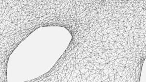
Let’s quickly break this down. Every model is built out of polygons, which are also called faces. These are the flat squares you see in polygonal models (non-CAD models). Every sigle polygon is the surface between 3 or 4 edges, and every one of these edges needs to have 2 polygons connected to either side of it.
Still wondering why we call models watertight, though? The reason is that if you were to fill an object up with water, a manifold model wouldn’t let a drop of it escape. This doesn’t have anything to do with whether a 3D object is water resistant or can survive being submerged for prolonged periods.
Non-manifold issues are often not visible at the modeling stage. The simplest way to check whether a model is printable is to use an analyzer software, like Netfabb or Meshmixer. These programs detect model features that will cause issues at the 3D printing stage and offer repair options (without impacting the overall geometry of the model).
Also when you upload a part to print with Protolabs Network, our automatic tools will check whether a design is printable with the most common 3D printing processes and we will show you the areas that have errors.
What are NURBS? Practical tips for printing smooth surfaces
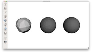
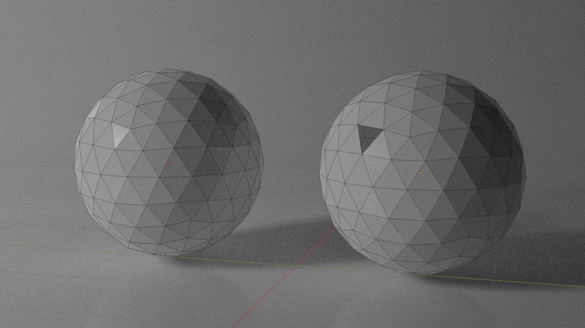
Most CAD modeling software, such as Solidworks and Fusion360, use Non-uniform Rational Basis Splines (NURBS) to display the surfaces of a 3D model. When exporting your model to the STL file format for 3D printing it’s important that an adequate number of polygons are used to represent its surfaces. This will ensure that your part will be 3D print with a smooth appearance.
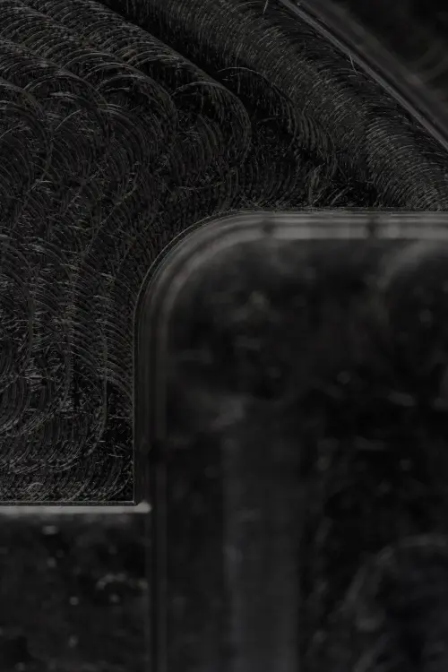
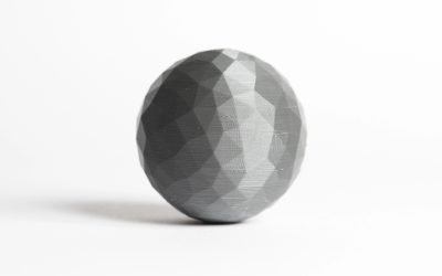
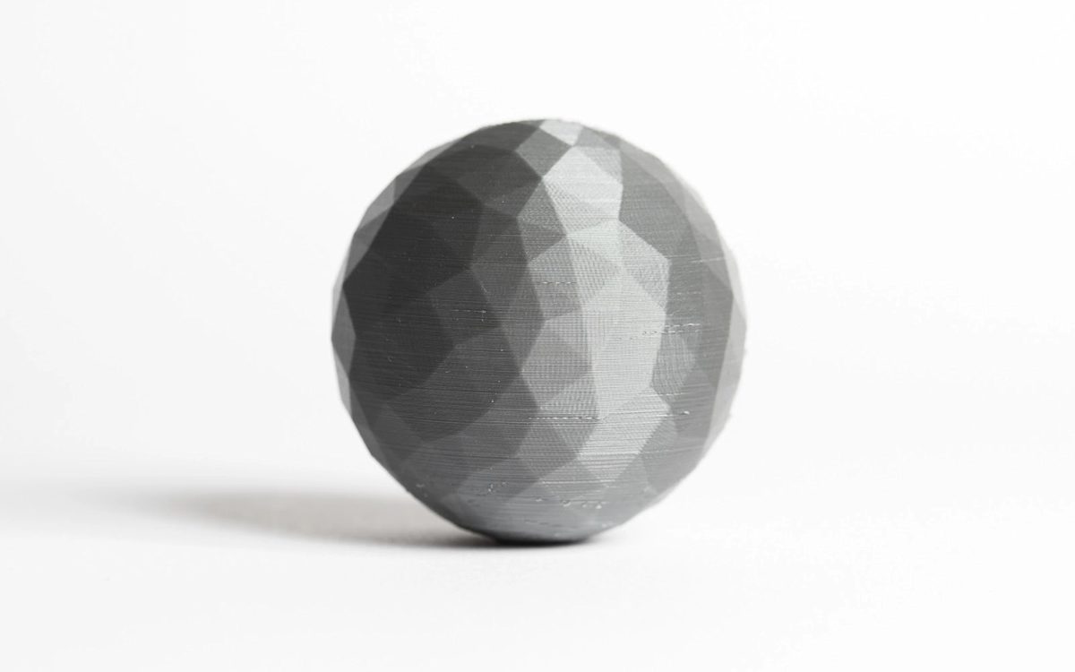
If the 3D model is exported with too few polygons, the edges connecting individual polygons will often be visible in the final 3D-printed part. This effect is more prominent with large models (larger than 300 mm3), where the polygons become more visible on curved surfaces.
If you export your 3D model with too many polygons, then the file size will be too large and difficult to handle for most printers. When you create meshes of polygons, the finer the mesh (meaning more polygons), the bigger the file size, so anything below that threshold will not print (or won’t print to the right quality level).
Luckily, most modeling software export 3D models with an adequate number of polygons using the preset, resulting in smooth 3D-printed parts. If a higher polygon count is required, the export settings can be adjusted accordingly.
Ready to explore what's possible with 3D print manufacturing?
Our online 3D printing service Upload a CAD file for a free, instant quote
