How to design parts for binder jetting 3D printing
A comprehensive guide on designing parts for Binder Jetting, covering the printing process, design specifications and material options.
Introduction
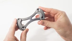
Binder Jetting is a 3D printing process with diverse capabilities that is capable of producing functional metal parts, full-color prototypes, figurines and large sand casting cores and molds. An introduction to the mechanics, characteristics and key benefits of Binder Jetting can be found here.
This article outlines the Binder Jetting 3D printing process, giving clear guidelines on designing parts for Binder Jetting and presenting the available materials and limitations of the process.
The Binder Jetting printing process
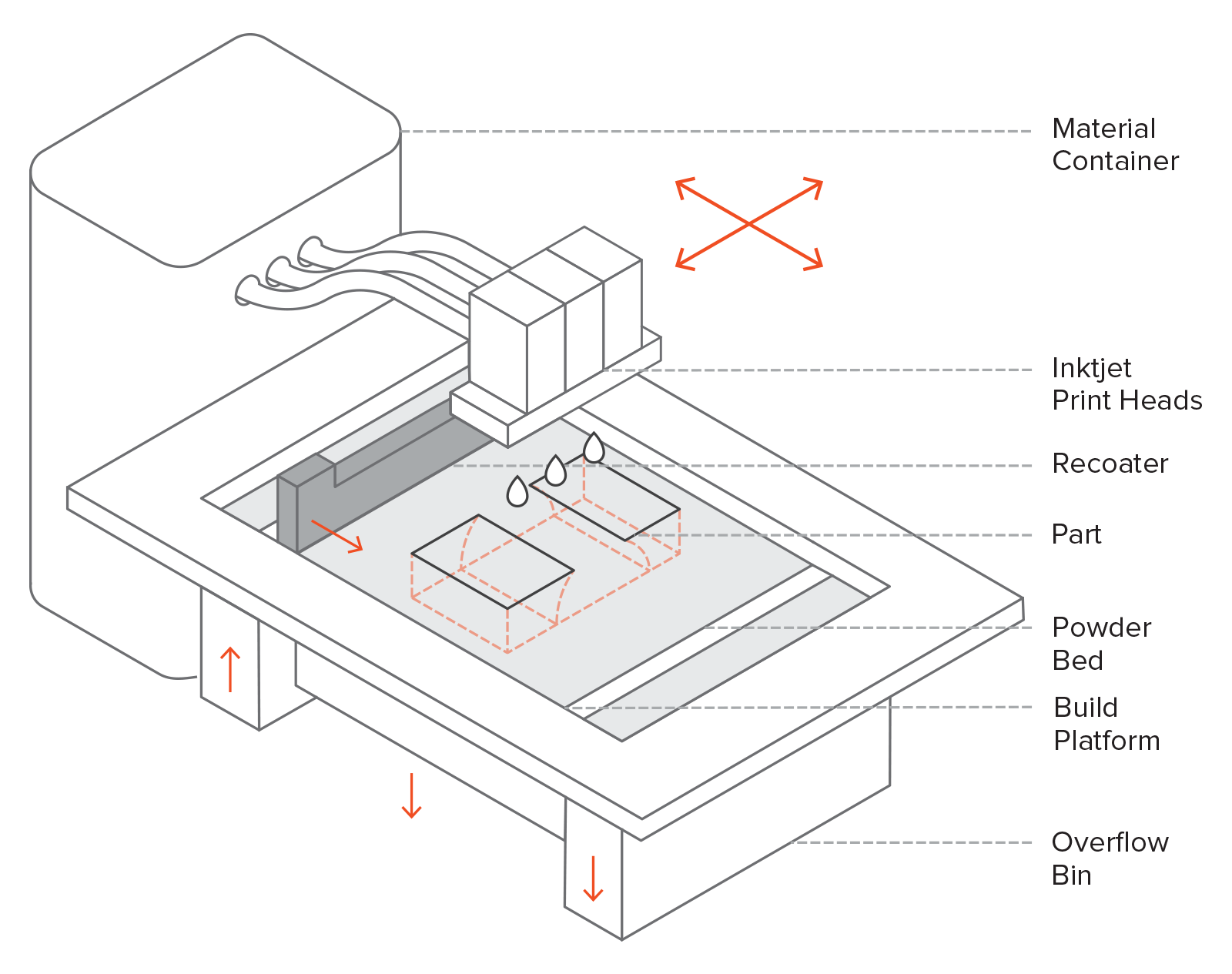
In Binder Jetting, an object is built by bonding powder articles together with an adhesive layer-by-layer.
The recoater first spreads a thin layer of powder over the bed and then several print heads equipped with inkjet nozzles (which are similar to the nozzles used in desktop 2D printers) selectively deposit an adhesive agent, binding the powder particles together and forming a layer. In the case of full-color prototypes, a coloring agent is also jetted on the powder during this step. The build platform then moves down one layer and the process repeats until the part is complete.
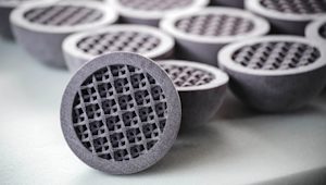
The materials used in Binder Jetting vary depending on the application from metals (like stainless steel and Inconel alloys) to plaster (sandstone) or PMMA for full-color prototypes and high-temperature silica sand for casting molds and cores.
Curious about prices and lead times for Binder Jetting services in your area?
Designing for Binder Jetting
Binder Jetting offers great design freedom, as the parts are printed at low temperatures. Errors connected with thermal effects, such as warping in FDM, SLS and DMLS/SLM, are not an issue in Binder Jetting. Moreover, there is no need for support structures, as the parts are fully encapsulated and supported by the surrounding powder, similar to SLS.
After printing, the parts are in a fragile green state and they usually need a post-processing step, like infiltration or sintering, before they are ready to use. This adds restrictions to the designs that can be printed with Binder Jetting, as thin features may break in the green state during handling.
Print Features
| Feature | Recommended minimum value |
|---|---|
 |
Wall thickness: 2.0 mm The recommended minimum wall thickness for parts produced via Binder Jetting is 2.0 mm. This ensures that the part can be removed from the powder and handled in the green state without being damaged. |
 |
Unsupported walls: 3.0 mm Unsupported walls (including fins or ribs) are at a greater risk of being damaged during handling and should not be thinner than 3.0 mm |
 |
Embossed and engraved details: 0.5 mm To ensure details are visible, embossed and engraved details should be at least 0.5 mm below or above the surface. |
 |
Unsupported edges: 2.0 mm Although the powder surrounding parts offers support during the build stages, unsupported edges are at a high risk of breaking during handling in the green state. Unsupported edges should be no longer than 20 mm. |
 |
Fillets: 1.0 mm All fillets should be a minimum of 1.0 mm radius and used in all edges of the design where possible. This ensures that they will not be damaged in the green state. Edges of metal parts can be sharpened after inflation/sintering. Radii are particularly important for internal cavities to aid in powder removal and accurate construction. |
 |
Hole size: Ø1.5 mm For a hole to be successfully printed the minimum diameter should be no smaller than 1.5 mm. |
 |
Escape holes: 5.0 mm Binder Jetting is able to produce parts with hollow sections. To remove unbound powder after printing, escape holes must be included to the design. Escape holes must be a minimum of 5.0 mm diameter and the use of at least 2 escape holes is recommended. |
 |
Feature size: 2.0 mm The main concern with Binder Jetting minimum feature size is the potential for damage. Although the process is able to produce parts with very fine details, it is the handling of the very brittle parts in the green state that is the issue. Because of this a minimum feature size of 2.0 mm is recommended. |
Green State
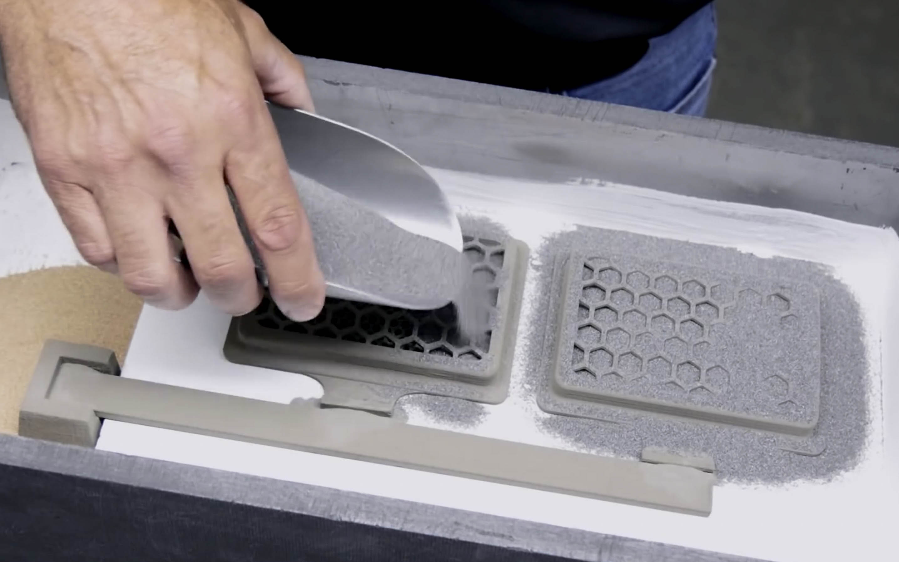
Out of the printer, Binder Jetting parts are in a fragile green state. At this point, the parts are very delicate as they are essentially comprised of sand or powder particles glued together.
If the part is too fragile to be handled in the green state, secondary post-processes cannot be applied to it. Post-processing typically involves removing the unbound powder from the surface of the part with brushes and pressurized air and then strengthening the part through an infiltration or sintering step.
It is important for the designer to adhere to the guidelines presented in table above to ensure that the parts are strong enough to survive handling during post-processing.
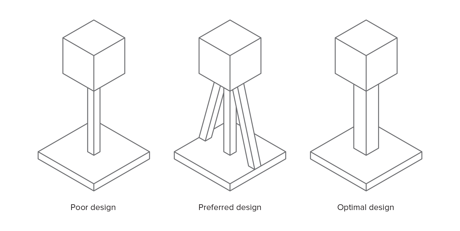
If a feature or detail is too fragile, one solution is to add extra bracing structures to the design to improve its stiffness and provide support. These bracing features can then be removed after infiltration or sintering (when the part is stronger), but this will add to the cost and time as an extra step is required. Of course, the optimal solution is to increase the dimensions of these features according to the recommendations of the table above.
Infiltration and Sintering
Binder Jetting is used to produce functional metal parts through secondary processes, like infiltration or sintering. The mechanical properties of full-color sandstone parts are also enhanced after printing through infiltration, usually with a cyanoacrylate adhesive (super glue) or another additive that can modify their properties. The rest of the section focuses on infiltration and sintering of metal parts, as they are of greater practical interest.
Infiltration:After printing, the part is placed in a furnace, where the binder is burnt out leaving voids. At this point, the part is approximately 60% porous. Bronze is then used to infiltrate the voids via capillary action, resulting in parts with low porosity (approximately 10%) and good strength.
Sintering:After printing is complete, the parts are placed in a high temperature (often microwave assisted) furnace, where the binder is burnt out and the remaining metal particles are sintered (bonded) together, resulting in parts with very low porosity (less than 3%).
Infiltration and sintering of metal Binder Jetting parts is connected with a large degree of shrinkage and dimensional reduction. The effect is more prominent is sintering, as no new material is added to the part.
Shrinkage is highly dependent on the geometry of the part. As a rule of thumb, parts with length up to 25 - 75 mm shrink between 0.8% to 2%, while larger parts have an estimated average shrinkage of 3%. Non-uniform shrinkage can be an issue and must be accounted for during the design stage in collaboration with the Binder Jetting machine operator.
Keep in mind that Binder Jetting metal parts will typically have some internal porosity even after infiltration (typically 90% dense) or sintering (typically 97% dense). This means that their mechanical properties will be inferior to the bulk material or to parts that were manufactured with a different 3D printing process, such as DMLS/SLM. Some more information can be found here. Metal Binder Jetting processes are advancing rapidly though and new systems that offer advanced capabilities are scheduled for release in 2018.
One aspect unique to the infiltration process is the need for stilts to allow bronze to infiltrate the part. Often it is the operator who will decide the best stilt location on a design. Stilts require a smooth surface to be placed on with a minimum surface area of 1.5 mm x 1 mm. It is important that a designer understands where stilts are placed as they must be removed after infiltration and this can have a detrimental effect on the surface the stilt was in contact with.
Full color printing
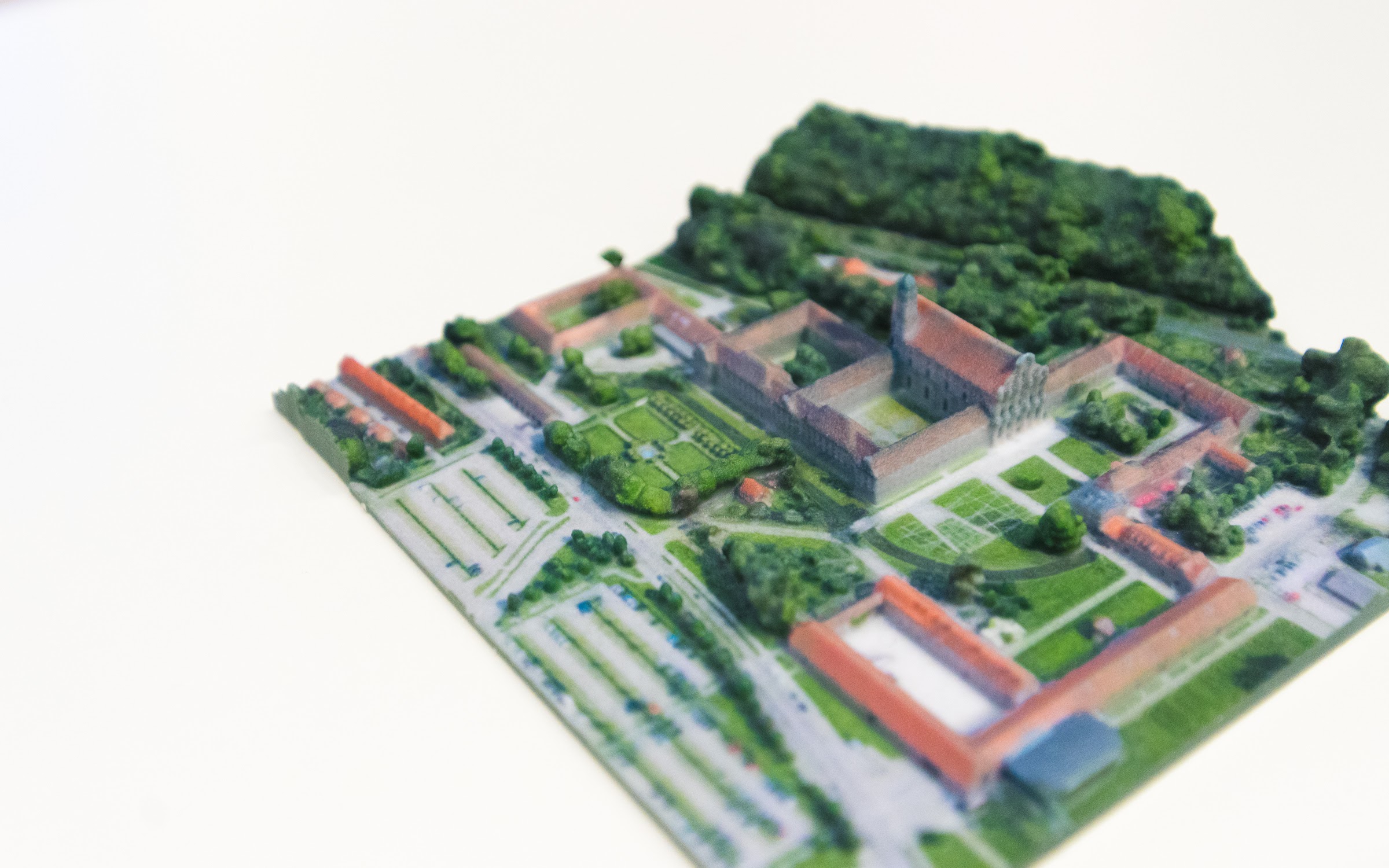
Binder Jetting produces full-color prints by jetting ink and binding agent onto the plaster (sandstone) or PMMA powder simultaneously.
After printing, the parts are coated with cyanoacrylate (super glue) infiltrant to improve part strength and enhance the vibrancy of the colors. A second epoxy layer can then also added to further improve strength and color appearance. Even with these extra steps, full-color Binder Jetting parts are very brittle and not recommended for functional parts.
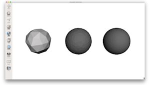
Color is applied to CAD models via 2 methods: on a per face approach or as a texture map.
Applying color to a model on a per face basis is quick and easy to implement but will result in less detail. Most CAD software packages allow color to be assigned to each face of a design and the file can then be exported as a VRML (Virtual Reality Modeling Language).
Using a texture map to apply color is much more complicated and must be approached on a per software basis. Texture files are generally JPEG or PNG format. Once all textures have been assigned the model is typically exported as a VRML or X3D file.
Binder Jetting materials
The following table summarises the characteristics of some of the most commonly used materials in Binder Jetting:
| Material | Description | Characteristics |
|---|---|---|
| Full Color Sandstone | Used for printing realistic, high definition, full-color concept models and prototypes. |
Full colour non-functional models
Very brittle
|
| Silica Sand | Used for a wide range of applications, including the creation of molds and cores for industrial castings. The advantage of using a common material such as silica sand for 3D printing is that it requires no changes at the foundry. |
Very high thermal resistance
Excellent for sand casting applications
|
| Stainless steel (bronze infiltrated) | Stainless Steel infiltrated with Bronze is a matrix material composed of 60% stainless steel and 40% bronze infiltrant. The lower yield strength of the material enables it to be easily machined and polished. |
Good mechanical properties
Can be machined
~10% internal porosity
|
| Stainless steel (sintered) | Stainless Steel is a corrosion resistant material that is easily machined and polished. This material offers high tensile strength and high temperatures resistance. |
Very good mechanical properties
High corrosion resistance
~3% internal porosity
|
| Inconel alloy (sintered) | Inconel is a nickel-chromium-based superalloy that offers excellent mechanical properties both at extremely high and low temperatures. It also exhibits high resistance to oxidation at elevated temperatures of up to 1050°C. |
Excellent mechanical properties
Good temperature resistance
High chemical resistance
|
| Tungsten carbide (sintered) | One of the hardest carbides with a melting point of 2770°C, Tungsten Carbide is mainly used in the production of high wear-resistant abrasives, carbide cutting tools (knives, drills and circular saws), and milling and turning tools used by the metalworking, woodworking, mining, petroleum and construction industries. |
Very high hardness
Used for the production of cutting tools
|
Post processing
Due to the nature of the Binder Jetting process, a limited number of post-processing methods is usually applied to the parts.
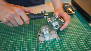
Metal Binder Jetting parts after infiltration or sintering can be sanded, polished or even machined to improve their appearance and dimensional accuracy. Other common metal finishes can also be applied to the parts, as they have high stiffness and are free from any binder.
Sand casting cores and molds are generally ready to use once they are removed from the printer and cleaned from the excess powder. Some binders do require thermal post-processing to improve strength.
Full-color models are generally dipped or coated with an infiltrant to improve their mechanical properties. Because Binder Jetting offers full-color printing, painting or dyeing is generally not required. Parts can also be coated in a clear lacquer to improve wear resistance and to give prints a smooth surface.
Common Binder Jetting applications
Some of the most common applications of Binder Jetting are presented below:
| Full color prototypes & figurines | The secondary processes that are used in conjunction with Binder Jetting (sintering or infiltration) allow for the production of functional metal parts. The large range of metals available and the ability to create complex shapes, make Binder Jetting a viable solution for designs that would be very expensive and difficult to produce traditionally. Binder Jetting is also has small batch production capabilities making it ideal candidate for low-run manufacturing of non-critical mechanical components. |
| Sand casting | The production of large sand casting patterns is one of the most common uses for Binder Jetting. The low cost and speed of the process make it an excellent solution for elaborate pattern designs that would be very difficult or not possible to produce using traditional techniques. Very large Binder Systems exist that are specifically designed for the production or large sand casting cores and molds (see overview table below). |
| Function metal parts | The secondary processes that are used in conjunction with Binder Jetting (sintering or infiltration) allow for the production of functional metal parts. The large range of metals available and the ability to create complex shapes, make Binder Jetting a viable solution for designs that would be very expensive and difficult to produce traditionally. Binder Jetting is also has small batch production capabilities making it ideal candidate for low-run manufacturing of non-critical mechanical components. |
| Grade | Description | Common applications |
|---|---|---|
| Grade 1 | Most ductile and corrosion-resistant, but lowest in strength | Chemical processing, marine systems |
| Grade 2 | Balanced strength and ductility. | Marine, industrial, and aerospace components |
| Grade 5 / Ti-6Al-4V | Alloyed grade with high strength and corrosion resistance | Aerospace, medical implants, high-performance parts |
Rules of Thumb
- Binder Jetting offers great design freedom, as no support structures are required and warping is not an issue, but the parts have to be strong enough to withstand handling in the green state.
- Binder Jetting can be used for diverse applications including the production of functional metal parts, sand casting molds and cores and full-color models and figurines.
- Metal Binder Jetting parts have some internal porosity even after infiltration or sintering (typically between 10% and 3%), so they are not suitable for applications that require high performance.
