How to design parts for metal 3D printing
A comprehensive guide for metal 3D printing covering the printing process, design specifications, material options and technology limitations.
A special thank you to Martin Petrak, MSc. P.Eng., Alan Rattan, M.Sc. EIT, Ryan Olson, EIT and Jared Kozub, P.Eng. of Precision ADM for producing the content for this article
Introduction
Metal 3D printing is a rapidly growing in popularity manufacturing process. Today, metal Additive Manufactured parts are designed for a large number of industry sectors (especially aerospace and medical applications) because they offer great freedom of design, component simplification or consolidation, decreased supply chains, and on demand bespoke or mid volume part production.
This article will offer a brief description of metal AM with respect to technology and materials, and elaborate on design considerations, benefits and limitations.

The metal printing process
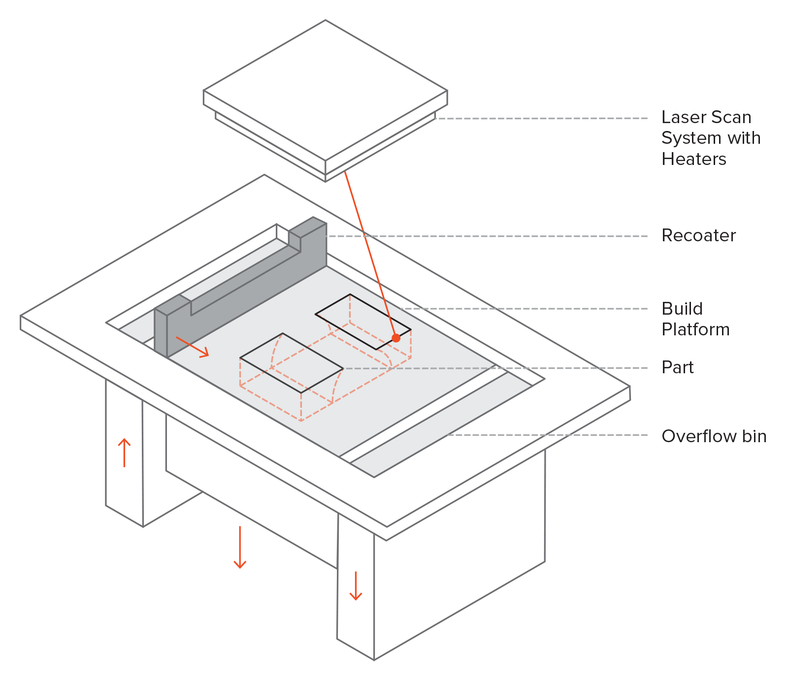
Direct Metal Laser Sintering (DMLS) and Selective Laser Melting (SLM) are powder bed fusion technologies that use a laser beam to fuse metal powder layer by layer. The layers or slices are the cross-sectional geometry of the part at a certain height, with many layers representing the entire part. The machine will apply a finite thickness of metal powder before exposure to the laser with the process repeating itself until all layers of the part have been exposed. As the laser fuses the metal powder, the current layer will also fuse to one or more of the previous layers. The size of the part and machine parameters will affect the time required to construct any three-dimensional part.
The main components and the general layout of a typical DMLS machine are shown in the image below. The laser beam scans across the top powder bed, exposing areas corresponding to the cross-section of the part at a certain height. The build platform will lower after the current layer has been exposed to the laser. The dispensing platform rises allowing the recoated blade assembly to sweep across from right to left, spreading a layer of metal powder across the powder bed. The collecting platform lowers to accommodate overflow powder as the recoater blade sweeps over top. This process repeats itself until the part is fully constructed, which may result from exposing thousands of layers that are microns in thickness. 3D printers like Markforged Metal X are at the forefront of this technology.
After fabrication, when the loose powder is brushed away, the part is cut away from the build platform via a band saw or wire EDM.
For this article the terms DMLS and SLM will be referred to as metal printing. Both classifications use the same technology to produce parts. The difference is that SLM achieves a full melt while DMLS sinters the powders. This means that DMLS only works with alloys (nickel alloy, Ti64 etc.) while SLM can use single component metals such as aluminum. Other metal printing technologies like electron beam melting (EBM) are out of the scope of this article.
Designing for metal printing
When designing parts for metal printing, there are a number of design recommendations that when followed, will help achieve better part quality, surface finish, and dimensional accuracy. Many of these design guidelines are dependent on the material and laser parameters, but staying within the geometric recommendations will help ensure that parts turn out as expected.
Designing for metal printing
General guidelines for designing metal printed parts are:
| Feature | Description |
|---|---|
 |
Wall thickness - The minimum wall thickness to ensure a successful 3D print with most materials is 0.4mm. Finer structures are possible, but are dependent on material, orientation, and printer parameters. |
 |
Pin diameter - The minimum reliable pin diameter is 1mm. Smaller diameters are possible, but will have reduced contour sharpness |
 |
Hole size - Holes diameters between 0.5mm and 6mm can be printed reliably without supports. Support free building of hole diameters between 6mm and 10mm is orientation dependent. Horizontal holes with a diameter greater than 10mm require support structures. |
 |
Escape holes - Holes are required on hollowed metal parts to remove unmelted powder. A bore hole diameter of 2-5 mm is recommended. Using multiple escape holes will greatly improve the ease of powder removal. |
 |
Overhanging Surfaces - The minimum angle where support material is not required on an overhanging surface is 45º relative to the horizontal in most cases. It is possible to reduce this angle further by optimizing the laser parameters. |
 |
Unsupported Edges - The maximum length of a cantilever-style overhanging surface is 0.5 mm. An overhanging horizontal surface supported on both ends can be 1 mm long. These rules will apply to embossed and engraved features with unsupported surfaces as well. |
 |
Aspect Ratio - The maximum ratio between the vertical print height and the part section is 8:1 to ensure stability of the printed part on the build plate. |
 |
Tolerances - Part tolerance in the print direction is ± 1-layer thickness. In the XY plane, the achievable tolerance is ± 0.127 mm |
Support material
Due to the high temperatures involved in the metal printing process and the layer by layer nature of part construction, support structures are required to connect unsupported geometry to the build platform and act as a heat sink for thermal energy. Support therefore plays is an essential factor to consider when designing for metal printing. Support performs 2 roles for parts made via metal printing:
- Metal printing melts or sinters layers of powder at a very high temperature. Because of this, each layer requires something “solid” to build upon, not just loose powder like the SLS process. To achieve this, for sections that are not attached to the build plate, support structures are first printed, then the solid sections built on top of these.
- Residual stress resulting from the differential cooling means that each layer of a metal print wants to curl up and distort. The addition of support helps to draw heat away from the recently printed sections as well as anchoring them down onto a solid base.

Support adds extra cost to a build (as it uses extra material) and also must be removed once the print is complete. Surfaces in contact with support always require some form of post-processing to achieve the same surface finish as parts where support was not needed.
Surface quality
Some designs require one side of the part to have a smooth surface (also known as the presentation side). If a smooth surface finish is desirable, post-processing is generally required. There are some steps that can be taken when selecting part orientation to improve the surface quality of a print. These include:
- Upward facing surfaces of a part will have sharper edges and better surface quality than downward facing surfaces. The greater than angle of a downward facing surface relative to the horizontal, the better the downward facing surface quality.
- A visible “stepped” effect can occur on angled surfaces depending on the layer thickness. In general, to avoid steps on the surface, the angle of the plane should be greater than 20º relative to the horizontal.
Metal printing materials
The table below identifies some of the more common metal printing materials and applications they are typically used for.
| Material | Description | Applications |
|---|---|---|
| Aluminum (AlSi10Mg) | Casting alloy with good strength and hardness. Used for its good combination of mechanical and thermal properties when low specific weight is a requirement. | Aerospace and automotive production parts |
| Maraging Steel (18 Mar 300 / 1.2709) | Martensitic hardening steel with good toughness, tensile strength and low warping properties. Can be easily machined, hardened, and welded. High malleability allows it to be formed easily for different applications. | Injection molding tools for series production and other mechanical parts. |
| Cobalt Chrome (UNS R31538 / ASTM F75) | Superalloy with excellent wear and corrosion resistance. Great mechanical properties at elevated temperatures. Wear resistance, corrosion resistance, and biocompatibility make it ideal in surgical implants and other high-wear applications. | Aerospace and medical (implants) production parts. |
| Stainless Steel (316L) | Austenitic chromium-nickel alloy with high strength and wear resistance. Good elevated temperature strength, formability and weldability. Used for its excellent corrosion resistance including pitting corrosion and chloride environments. | Aerospace and medical (surgical tools) production parts. |
| Stainless Steel (15-5 PH) | Precipitation-hardened stainless steel with excellent strength, toughness, and hardness. It's good combination of strength, fabricability, ease of heat treatment, and corrosion resistance makes it a popular material that is used in many industries. | Production parts for various industries. |
| Stainless Steel (17-4 PH) | Precipitation-hardened stainless steel with excellent strength and fatigue properties. It's good combination of strength, fabricability, ease of heat treatment, and corrosion resistance makes it a commonly used steel in many industries. 17-4 PH Stainless steel contains ferrite, while 15-5 Stainless Steel is ferrite-free. | Production parts for various industries. |
| Titanium (Ti6Al4V / Grade 5) | Excellent mechanical properties and corrosion resistance with a low specific weight. Most common titanium alloy used for its excellent strength-to-weight ratio, fabricability, and ability to heat treat. | Aerospace and automotive (motorsports) production parts. |
| Titanium (Ti6Al4V / Grade 23) | Excellent mechanical properties and corrosion resistance with low specific weight. Excellent strength-to-weight ratio, fabricability, and biocompatibility. Improved ductility and fatigue strength make it widely used for medical implants. | Medical (implants) production parts. |
| Nickel Alloy (Inconel™ 718 / UNS N07718) | Super alloy with excellent yield, tensile, and creep-rupture strength at high temperatures. Used for high strength applications in extreme environments. Excellent weldability compared to other nickel-based super alloys. | Aerospace (high-temperature turbine components) production parts. |
| Nickel Alloy (Inconel™ 625 / UNS N06625) | Superalloy with excellent strength and toughness at high temperatures. High corrosion resistance. Used for high strength applications in extreme environments. Extra resistant to pitting, crevice corrosion, and stress-corrosion cracking in chloride environments. | Aerospace (high-temperature turbine components) production parts. |
| Nickel Alloy (UNS N06002 / Hastelloy X) | Superalloy with exceptional combination of high-temperature strength, fabricability, and oxidation resistance. Used for high strength applications in extreme environments. Resistant to stress-corrosion cracking in petrochemical environments. Excellent forming and welding characteristics. | Production parts in severe thermal conditions and high risk of oxidation (combustion chambers, burner and supports in industrial furnaces). |

Process limitations
Cost
The cost of both metal AM machines and the materials they use are very high. Because of this, for some applications, traditional manufacturing techniques may be the most cost-effective solution (metal AM is unsuitable for the production of lots of generic washers/fasteners or large parts that are typically fabricated). Metal AM strength lies in complex, bespoke manufacturing where a high level of customization is required, or geometries are needed that traditional manufacturing techniques are unable to produce. To remain cost-effective, most metal AM machines need to be producing parts as often as possible with very little idle time.
Design for additive manufacturing (DFAM)
One of the biggest misconceptions for metal AM is that all applications designed for conventional manufacturing can be converted to an AM solution. If a part was originally scoped and designed for conventional manufacturing, then it is more likely not a great candidate for 3D printing for a number of reasons. If a simple part has a large part size to part complexity ratio, then the manufacturing time to build is relatively high without the added value or improved function capable of a part designed for AM.
Product size
Even the largest metal AM machines have a small build volume when compared to conventional manufacturing build sizes. The average build volume size is approximately 250 mm x 250 mm x 300 mm (x × y × z).
Machine complexity
Metal additive manufacturing systems are not plug-and-play much like many polymers systems that exist on the market today. Most metal AM machines are industrial in size and require strict operating, material handling, post-processing and maintenance procedures.
Post processing
The most common post processing methods for metal printing are:
- Heat treatment
- Support removal
- Machining
- Surface treatment

Rules of thumb
- Support is a critical part of the metal printing process and the geometry, placement and the amount used should be optimized to save on time and cost.
- Part orientation should be considered during the design stages. Upward facing surfaces will have sharper edges and a better surface finish.
For designing metal printed part features:
| Feature | Design specifications |
|---|---|
| Wall thickness | Minimum 0.4 mm in width. |
| Pin Diameter | Greater than 1.5 mm diameter. |
| Hole Size | Diameters between 0.5 mm and 6 mm without supports. Diameters greater than 6 mm will mostly require supports. |
| Escape Holes | Minimum 2-5 mm in diameter. |
| Overhangs | Greater than 45° from horizontal for unsupported surfaces. |
| Unsupported Edges | Maximum 0.5 mm. |
| Aspect Ratio | 8:1 build height to section width |
| Tolerances | ± 1-layer thickness in Z-direction. ± 0.1 mm in XY plane. |
