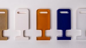
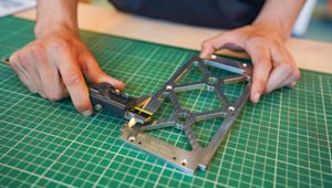
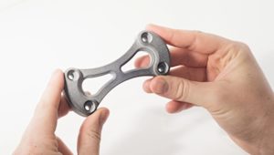
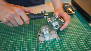
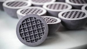
Selective laser sintering (SLS) 3D printing is ideal for producing functional products with complex geometries. Compared to other 3D printing technologies, the solution has very few design constraints and is also suitable for batch manufacturing.
This article discusses the advantages of using SLS to 3D print parts. It presents the most common SLS materials and offers rules for designers to follow when printing with SLS.
Essential bonus: Download our free “Design rules for 3D printing” poster in high resolution, full of actionable guidelines for the six major 3D printing processes.
What is the SLS printing process?
SLS is a powder bed fusion technology that uses a laser beam to locally sinter polymer powder, building parts layer by layer.
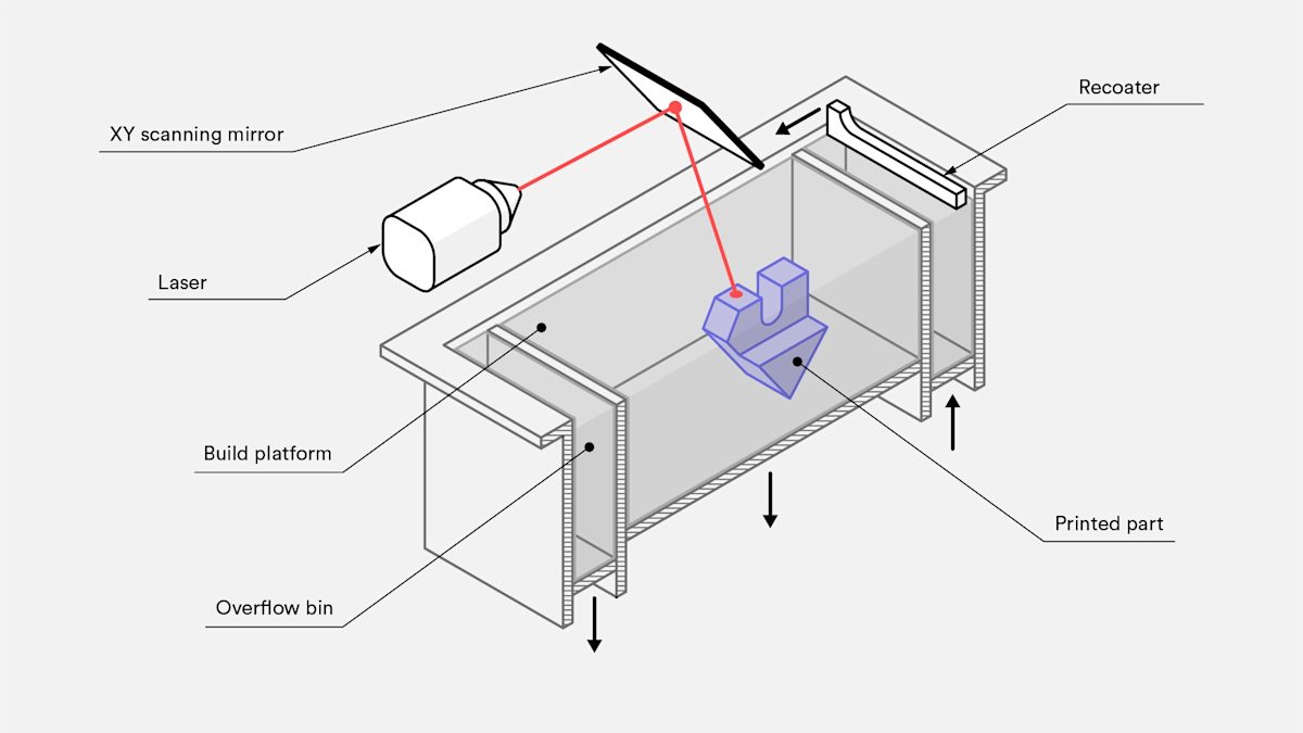
To begin, a bin of the powder material is heated to an elevated temperature. A recoating blade deposits the powdered material in a very thin layer (typically 0.1mm) onto a build platform. After a layer is deposited, a laser beam starts scanning the surface. The laser beam selectively sinters the powder and solidifies a cross-section of the part. Once the entire cross-section is scanned, the building platform moves down one layer thickness in height. Unsintered powder remains in place to support subsequent layers, eliminating the need for support structures. The recoating blade deposits a new layer of powder on top of the scanned layer and the laser beam starts to sinter the successive cross-section of the part onto the previously solidified cross-sections. This process repeats until all parts are fully manufactured.
The result is a container filled with powder and consolidated products. The process is suitable for batch manufacturing because multiple products can be produced simultaneously. Optimize part placement and orientation to maximize the number of parts you can get in the powder box during each print.
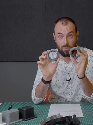
Want to see SLS 3D printing in action? Check out this 10-minute video about how to use SLS to make strong functional parts.
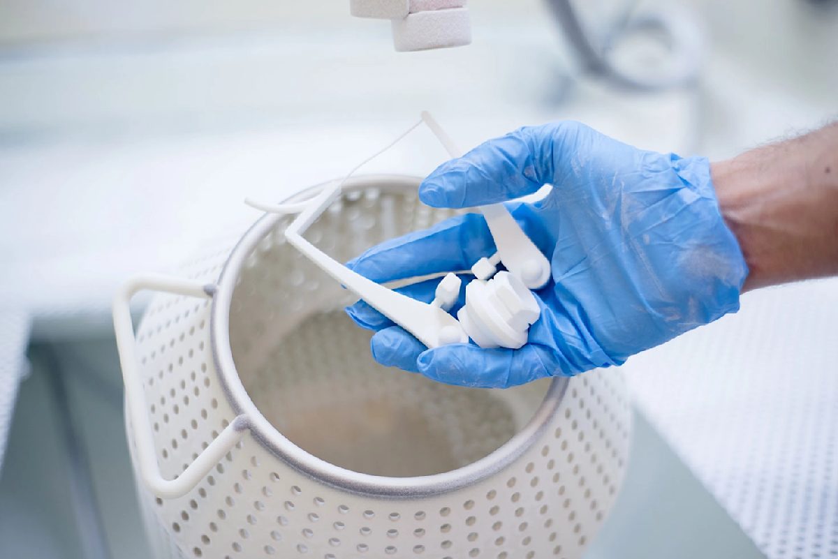
Once the printing process is complete and the powder container and product have cooled, the powder container is unpacked. Solid products are separated from the unsintered powder and cleaned using compressed air and a blasting medium. The remaining unsintered powder is collected and reused. The parts are then ready for use or can be post-processed to improve mechanical properties or appearance.
How do you design for SLS printing?
There are several design recommendations to improve quality, surface finish and functionality of SLS parts. One of the greatest advantages of using SLS is that it does not require support structures. The unsintered powder surrounding the part eliminates the need for support, allowing highly complex, intricate designs to be printed.
Print features
General guidelines for designing SLS parts are as follows:
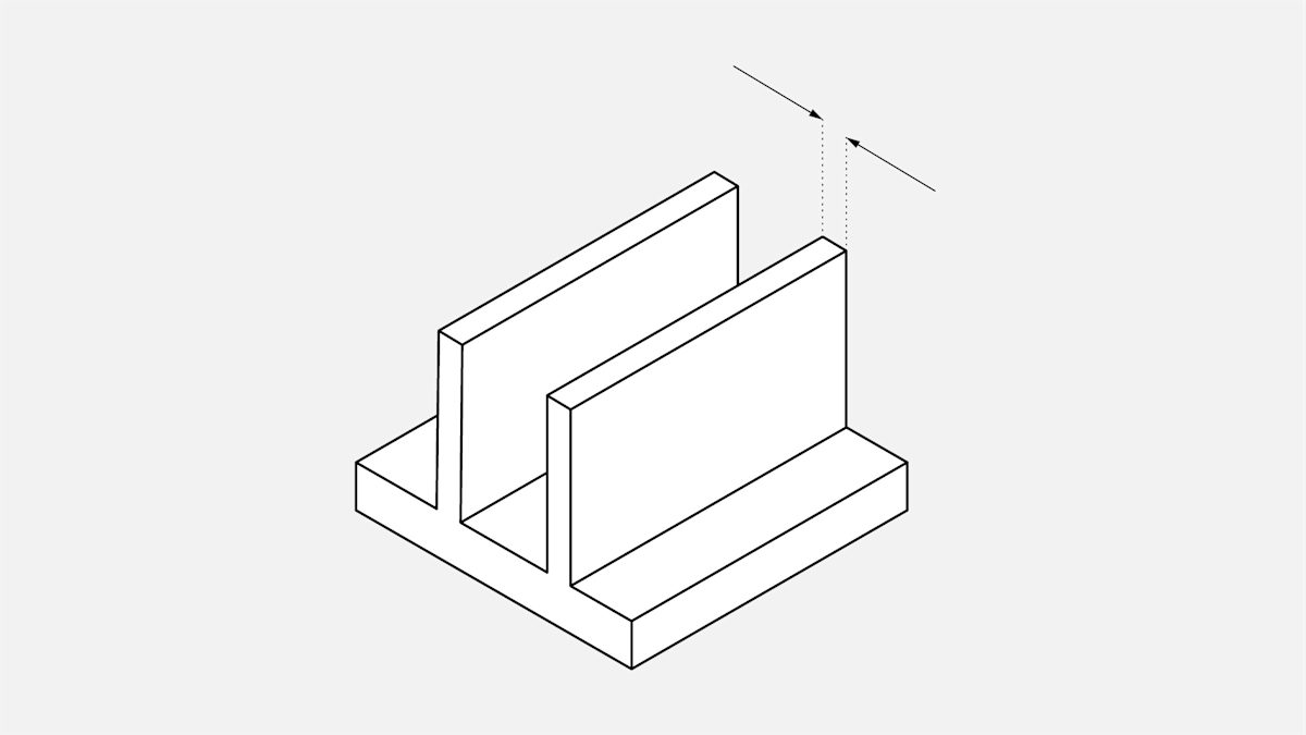
Wall thickness:
To ensure a successful 3D print, minimum thickness should be between 0.8mm (for PA12) and 2.0mm (for carbon-filled polyamide).
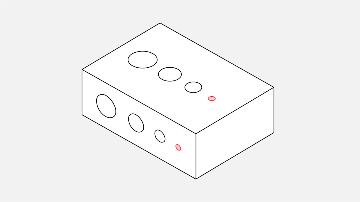
Hole size:
All holes should be larger than 1.5mm in diameter.
Escape holes:
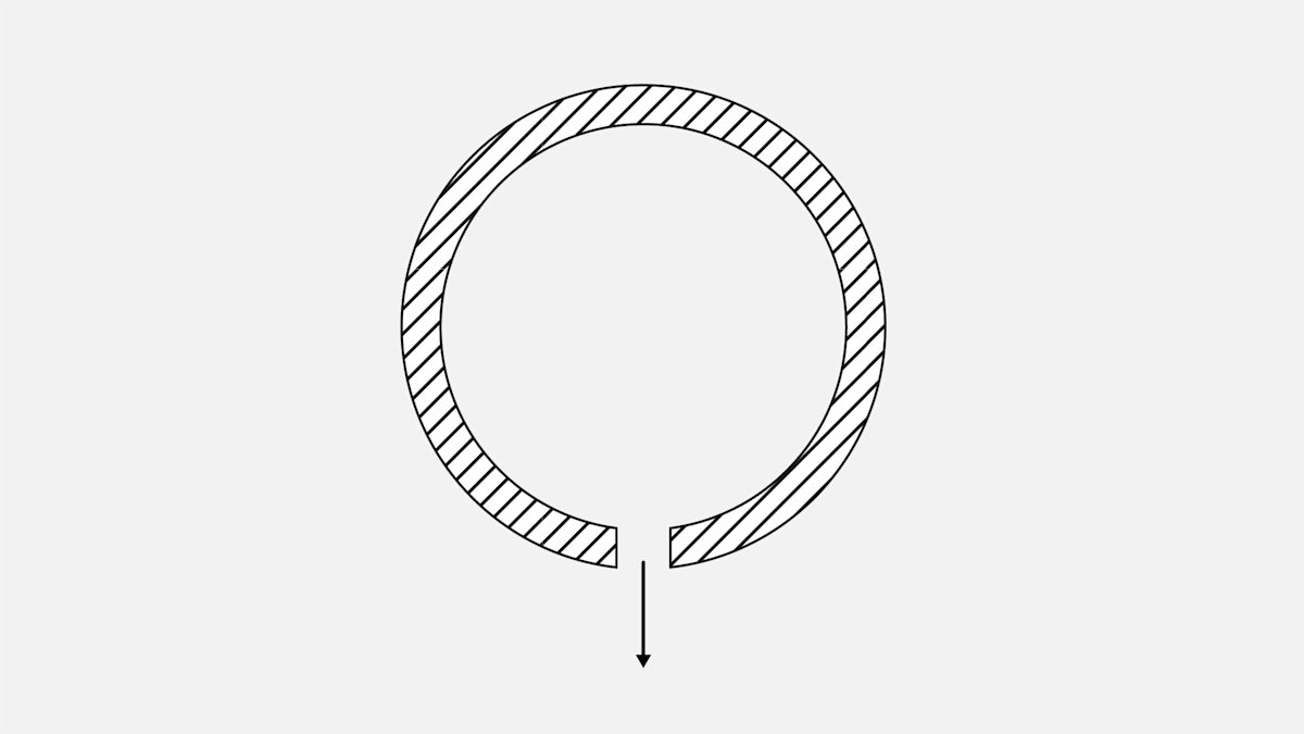
To save in weight (and sometimes cost), SLS parts are printed hollow. To remove unsintered powder after production, it is necessary to include escape holes, which must be a minimum of 3.5mm in diameter.
Feature size (pins, protruding features, etc.):
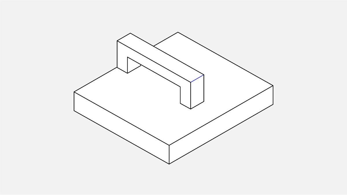
A minimum of 0.8mm is recommended.
Embossed and engraved details:
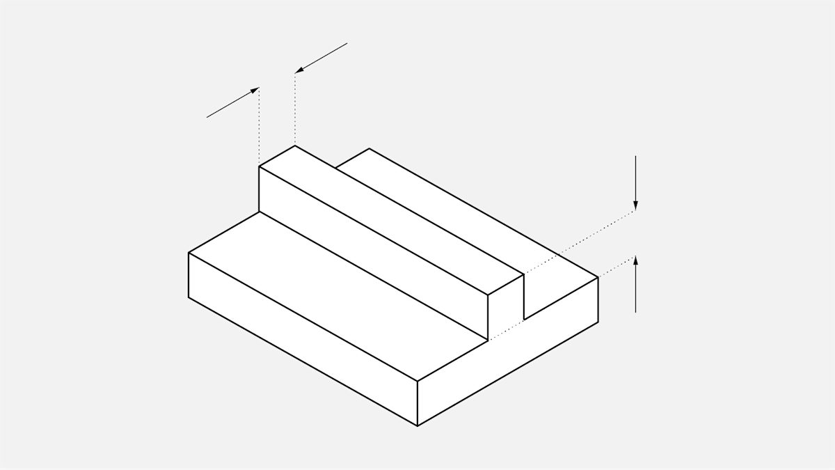
To ensure small details are visible:
- make minimum engraving depth 1mm.
- make minimum embossing height 1mm.
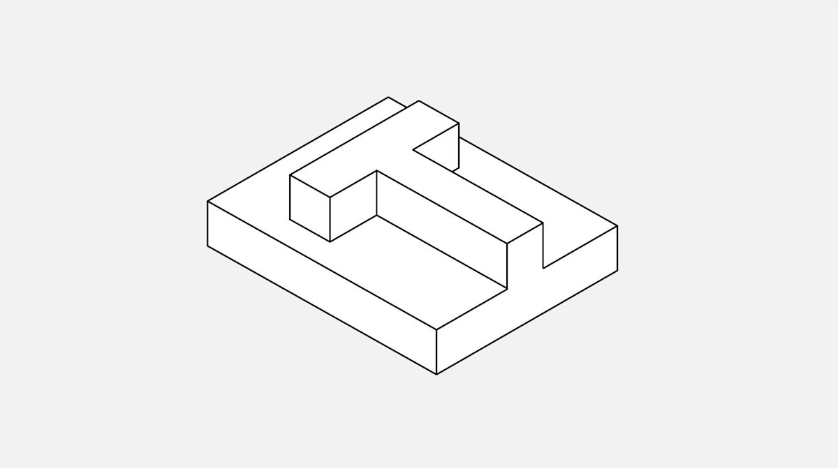
Text:
For readability:
- ensure minimum font height is 2mm (font size 14) and suitable for every direction.
- sans serif font is recommended.
Tolerances:
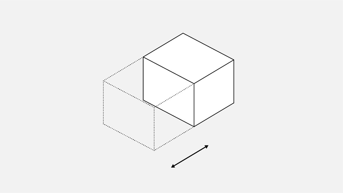
Typical tolerances for SLS parts are 0.3% with a lower limit of ± 0.3 mm (± 0.012 in)
Common design applications
Some of the most common design applications for SLS and several rules to help ensure a better quality part are as follows:
| Application | Description |
|---|---|
| Axles | Nylon as a natural bearing material provides a smooth, low-friction mechanism for low-load, low-velocity applications. For running axles, a bearing surface clearance of 0.3mm is recommended. It is important to remember that powder must be removed after the printing process to ensure a smooth running shaft. Wherever possible, include escape holes (of a minimum 3.5mm in diameter). Between the running shaft axle and clearance shaft hole, 2mm is recommended to allow for powder removal. |
| Integrated hinges | Integrated hinges can work very well with SLS nylon when properly designed. A trapezoid shaped pocket that accepts a semi-spherical ball allows for low friction and sufficient stability. Between the sphere and the pocket, 0.2mm of clearance is recommended. Between all other gaps, 0.3 mm clearance is recommended. |
| Interlocking parts | For design advice on interlocking parts for 3D printing, refer to this article. |
| Tanks | SLS nylon offers good chemical resistance and is often implemented in custom tank design. For extra watertightness or when using aggressive fluids, such as fuel or solvents, the tank can be coated or lined. A wall thickness greater than 1mm is recommended. Excess powder must be able to be removed from inside the tank. |
| Threads | The rough surface produced by SLS printing results in increased friction, and can cause some issues when connecting threaded SLS parts together. It is possible to drill and tap SLS nylon. An ideal solution is using SLS nylon for just one of the threaded connections (either the hole or the bolt). If the connection is critical to the part’s function, consider one of these methods for securing 3D-printed parts. |
| Living hinges | SLS is one of the only 3D printing methods that can produce functional living hinges. For SLS hinges, anneal the hinge by heating (dipping it in boiling water usually suffices) and then flexing the hinge back and forth. Living hinges are recommended to be 0.3-0.8mm thick and a minimum of 5mm long. |
Comparison with injection molding
In industrial design, SLS 3D printed parts are often used as prototypes for determining form, function and fit of designs to be mass manufactured by injection molding. The main differences between designing parts for SLS and injection molding are as follows:
-
Since an SLS part need not be removed from a dye, SLS can easily produce undercuts, negative draft and interior features.
-
SLS eliminates the need for costly tooling, which makes it cost-effective for production in small series (1-1,000).
-
SLS cannot produce perfectly sharp edges and corners. The SLS process produces parts with a radius of ±0.4mm at all edges and corners. A radius of less than 0.4mm on a design is printed as 0.4mm.
-
The natural radius produced by SLS offers some stress relief. For areas of concern, a larger radius (greater than 2mm) should be added.
Shrinkage and warping
The high temperatures SLS components experience during printing can cause some shrinkage and warping. To limit their impact, SLS parts are typically cooled slowly.
-
To accommodate shrinkage, most designs for SLS printing have overall dimensions increased by 3-3.5% at the pre-print analysis and conversion stage. This does not affect a part’s design.
-
To reduce the likelihood of warping—which large flat surfaces are prone to—consider adding ribs to increase stiffness. Part orientation during the printing stage can also help.
SLS materials
SLS can be used with different materials, the majority being polyamide-based. Polyamides are synthetic thermoplastic polymers, more commonly known as nylons. This table describes the most common materials printed with SLS.
| Material | Characteristics |
|---|---|
| PA12 | This material’s mechanical properties are comparable to injection molded polyamide, with high dimensional stability, wear resistance and chemical resistance. |
| Polyether block amide (PEBA) | This thermoplastic polyamide elastomer (TPA) is a strong, yet flexible rubber-like material. |
| Alumide | This aluminum-filled polyamide is characterized by high stiffness and good post-processing abilities. |
| Carbon-filled polyamide | This material is characterized by high stiffness and strength. |
| Glass-filled polyamide | This material is characterized by high stiffness and wear resistance. |
| PA11 | This environmentally friendly material is characterized by high-impact resistance and elongation at break. |
| PEEK | This material has excellent mechanical properties, high temperature resistance and potential for biocompatibility and sterilizability. |
What are the limitations of SLS 3D printing?
Product size
The size a part can be printed is determined by the size of the nylon container used in the SLS machines. The current average build volume is around 300mm x 300mm x 300mm. Bigger machines offer a build volume of 700mm x 380mm x 580mm.
Consistency
Since every SLS-printed part consists of hundreds—if not thousands—of layers, small variations, such as in dimension or surface quality, can occur. Each product’s singularity means most post-processing steps are done manually, which can also cause minor variations, such as in color or coating.
Surface finish
While SLS produces a consistent finish, the surface appears as a satin-like matte that is slightly grainy to the touch. If a shiny smooth finish is desired, post-processing is recommended.
Post-processing
The most common SLS post-processing methods are:
-
Standard finish
-
Media tumbled (Vibro polish)
-
Dyeing
-
Painting
-
Nickel plating
The addition of coatings can also improve the functionality of SLS parts, resulting in:
-
UV protection
-
Chemical resistance
-
Decreased gas permeability
-
Color protection
-
Increased wear resistance
-
Oil, water and saltwater resistance
For detailed information, reach this article about each post-processing finish offered for SLS parts.
What are the best practices for SLS design?
-
SLS parts do not require support, allowing for greater design freedom and making SLS one of the easier 3D printing technologies to design for.
-
SLS can produce many functional features, including axles, threads, tanks and hinges. Coupled with the range of available engineering polyamides, this makes SLS commonly used to produce end-use parts.
-
The standard surface finish for SLS is a matte-like grainy surface. A range of available post-processing options can also help improve part functionality.
Design specifications for SLS features
| Feature | Design specifications |
|---|---|
| Wall thickness | 0.8mm-2.0mm, depending on material |
| Hole size | Greater than 1.5mm in diameter |
| Escape holes | Minimum of 3.5mm in diameter |
| Text | Minimum font height of 2mm |
| Feature size | Minimum size of 0.8mm |
| Embossed and engraved details | Minimum engraving depth of 1mm and minimum embossing height of 1 mm |
| Tolerances | ±0.3mm (±0.012 in.) plus ±0.05mm (±0.002 in.) for each additional 25mm |
Want to learn more about 3D printing? Read our full guide: What is 3D printing?
Thanks to our manufacturing partner Oceanz for supplying information for this article.
