
3D printing involves more design considerations than many engineers expect. One of the most important, and often overlooked, is part orientation, also known as build orientation. The chosen orientation affects dimensional accuracy, mechanical strength, surface finish, and print time, and can ultimately determine whether a part meets its performance and quality requirements.
This article explains how build orientation affects dimensional accuracy, build time, mechanical performance, and surface finish in 3D printing. By the end, you’ll understand why choosing the right build orientation is essential for producing reliable, high-quality parts.
Curious about the cost of 3D printing custom parts?
Explore our 3D printing services Upload your CAD file for a free, instant quote
How does part orientation affect accuracy?
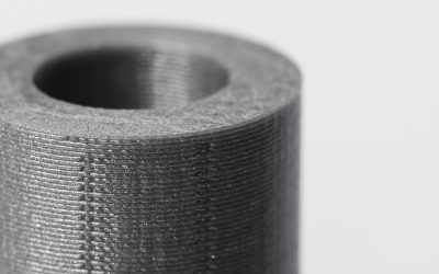
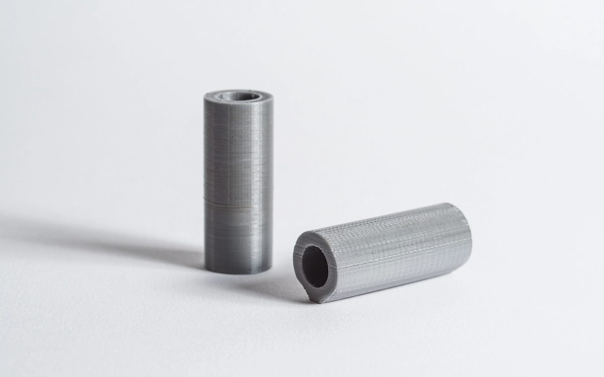
To illustrate how build orientation affects dimensional accuracy, consider an FDM-printed cylinder with a 10 mm outer diameter, a 6 mm inner diameter, and a length of 30 mm, oriented with its central axis vertical. In this orientation, the printer deposits concentric layers, resulting in a relatively smooth and accurate cylindrical surface.
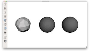
If the same cylinder is reoriented with its central axis horizontal, it is built as a series of stacked layers with varying widths. This increases the faceting effect on the circular profile and reduces dimensional accuracy. In addition, the surface in contact with the build platform will be flattened, further altering the part geometry. Orienting the part in different directions can significantly affect overall 3D print quality.
How does part orientation affect print time?
Build orientation can significantly affect print time. Using the same cylinder, the horizontal orientation prints faster because the Z height is shorter, which reduces the number of layers. At a 100 µm layer height, the horizontal build uses about 100 layers, while the vertical build uses about 300 layers. For larger parts, this difference can significantly change total build time.
How does part orientation affect strength?
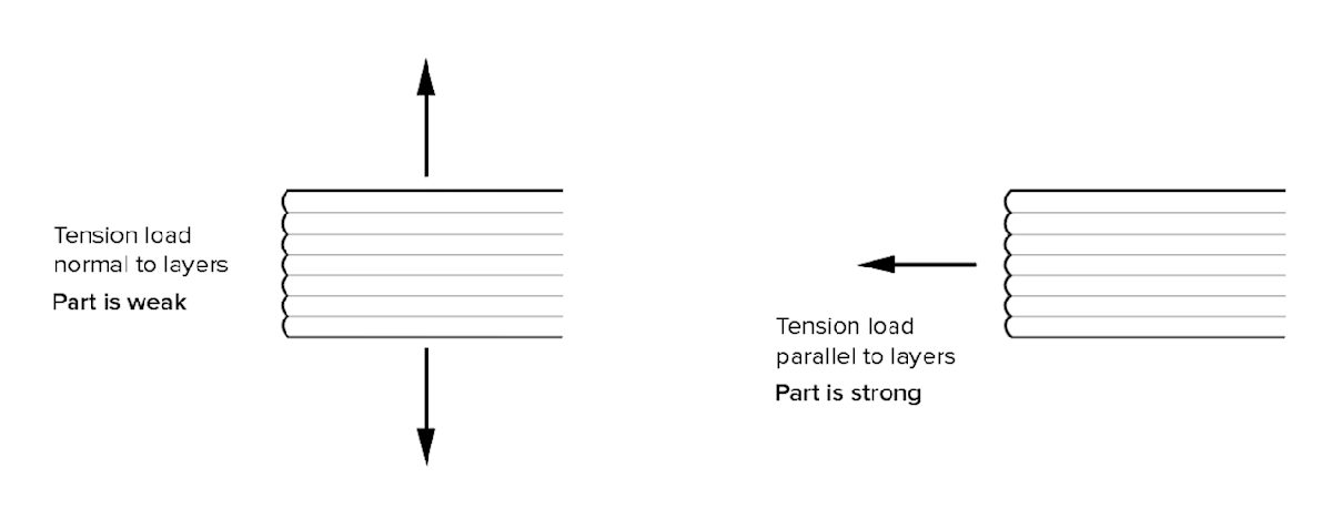
Some 3D printing processes, notably FDM, produce anisotropic parts that are much stronger in the XY plane than in the Z direction. For functional parts, consider the application and load direction relative to build orientation. FDM parts are anisotropic. Tensile strength in the XY plane is typically 4 to 5 times higher than in the Z direction, so Z tension increases the risk of delamination and fracture.
Assessing load paths: Tension, shear, and bending
To optimize your design, you must align the part’s internal ‘grain’ with the expected load paths. In FDM printing, the bond between layers is always weaker than the plastic strands themselves.
-
Tension: If a part will be subjected to tensile loads, orient it so that the printed layers run parallel to the direction of the force. Avoid orientations where the load acts perpendicular to the layers (along the Z-axis), as this can significantly reduce strength and increase the risk of layer separation or delamination.
-
Bending: When a part is subjected to a bending load, the outer walls or shells experience the highest stress. Orient the part so the continuous shell lines run along the length of the bend, helping improve strength and reduce the risk of layer separation.
-
Shear: For parts like pins or bolts, a horizontal orientation ensures the shear force has to cut across thousands of solid plastic strands, rather than simply sliding two layers apart.
How do support structures factor in?
Support material increases print time, material use and post-processing cost. Engineers optimize build orientation to reduce supports, improve stability and lower the risk of print failure. Optimizing support structures is a critical step in 3D printing that requires careful planning. That is why we provide a comprehensive guide to support strategies and materials.
How does part orientation affect surface finishes?
Upward-facing surfaces usually achieve the best finish, though results vary by 3D printing process.
-
In FDM, the upward-facing surface is smoothed by the nozzle, the bed-contact surface is typically glossy, and surfaces built over supports show support marks.
-
For SLA, downward-facing surfaces carry support marks and require post-processing, while top surfaces are smooth and free of support artifacts.
-
In powder bed processes such as SLS and MJF, lower surfaces typically exhibit a grainier finish.
Optimizing strength with shells and infill patterns
A common misconception is that increasing infill density is the best way to make a part stronger. In reality, 3D print part orientation allows you to leverage ‘Sandwich Panel Theory’. This principle states that the outer surfaces (the shells) contribute far more to flexural strength and rigidity than the internal core.
Instead of using 100% infill, it is often possible to create a stronger and lighter part by increasing the number of wall perimeters (shells) and selecting a build orientation that maximizes the length of these continuous paths. Parts with thicker shells and a lower-density gyroid infill can outperform fully solid parts, as they place material where stresses are highest, along the outer surfaces, while reducing weight and material consumption.
Beyond plastic: Continuous fiber reinforcement (CFR)
When standard engineering plastics such as Nylon or Onyx reach their performance limits, Continuous Fiber Reinforcement (CFR) can provide a significant increase in strength and stiffness. By embedding continuous strands of carbon fiber, Kevlar, or fiberglass within the printed layers, manufacturers can produce parts with mechanical properties that rival those of aluminum.
However, fiber orientation is even more critical than build orientation alone. Continuous fibers only reinforce the part along their length, meaning they must be aligned with the primary load paths to be effective. If the fibers are oriented incorrectly, they add weight with little structural benefit. Proper part orientation ensures that the reinforcing fibers are placed where stresses are highest, maximizing strength and performance.
Isotropy vs. Anisotropy: FDM vs. SLA vs. SLS
Whether you need to consider build orientation depends on your chosen technology, as each process handles layer bonding differently. In FDM printing, orientation is paramount as these parts are inherently anisotropic. Since layers are mechanically stacked, strength in the XY plane is typically 4 to 5 times higher than in the Z direction. For FDM, orientation and structural integrity are inextricable. A poor choice can therefore lead to immediate failure along the layer lines.
SLA (Stereolithography) offers more flexibility. While it is still a layered process, covalent bonds form between layers during the resin curing stage. This makes SLA parts ‘semi-isotropic’, meaning mechanical strength is much more uniform than in FDM. While orientation still dictates surface finish and support placement, the risk of structural weak points between layers is significantly lower.
Powder bed technologies such as SLS and MJF offer the most design freedom, as these are the least sensitive to orientation. These processes use high-powered lasers or fusing agents in a heated chamber to achieve near-total fusion of the material. This results in effectively isotropic parts. In these systems, you can orient components primarily to maximize tray density or surface smoothness without compromising the mechanical integrity of the design.
Use the table below as a quick reference to see how orientation impacts parts differently across major 3D printing technologies.
| Feature | FDM (Filament) | SLA (Resin) | SLS / MJF (Powder) |
|---|---|---|---|
| Structural Integrity | Anisotropic: High dependency. Z-axis is significantly weaker. | Semi-Isotropic: Moderate dependency; chemical bonds help layers. | Isotropic: Low dependency; parts have uniform strength. |
| Surface Finish | High impact (visible layer lines and stepping). | High impact (support marks vs. smooth top faces). | Minimal impact (uniform grainy texture). |
| Print Speed | Driven by layer count (Z-height). | Driven by layer count (Z-height). | Driven by Z-height and nesting density. |
| Supports | Essential for overhangs >45°. | Essential for nearly all overhangs. | None required (self-supporting powder). |
| Best For | Functional parts (if aligned with load). | High-detail visual prototypes. | Complex geometries & batch production. |
Get started
Ready to optimize part orientation for strength, accuracy, and surface finish? Upload your design for a free, instant quote with process recommendations and DFM feedback.
Frequently asked questions
What is part orientation in 3D printing?
Part orientation is a critical build parameter in additive manufacturing for rapid prototyping. It controls support volume, surface finish, anisotropy, and build time, which directly affects print quality and throughput in outsourced 3D printing for engineers.
Will part orientation affect the cost of 3D printing?
Yes. Part orientation affects 3D printing cost. In outsourced additive manufacturing, orientation drives support structure volume and build height, which determine material use, machine time, and post-processing. Large overhangs and acute angles increase required supports, raising resin or filament consumption and extending cycle time.
Taller orientations add layers and risk, which can reduce yield. Optimized orientation lowers support, shortens builds, and reduces failure probability. This impact is most pronounced in FDM 3D printing and SLA 3D printing, where support removal and surface finishing add labor to cosmetic faces.
Is it better to 3D print vertically or horizontally?
Geometry and process drive the choice. For most FDM and SLA parts, a horizontal orientation shortens build time and reduces supports, while cylindrical features often print best vertically to improve roundness and surface finish.
Which 3D printers produce isotropic parts?
For isotropic parts, with mechanical properties uniform in every direction, we recommend SLA or MJF.